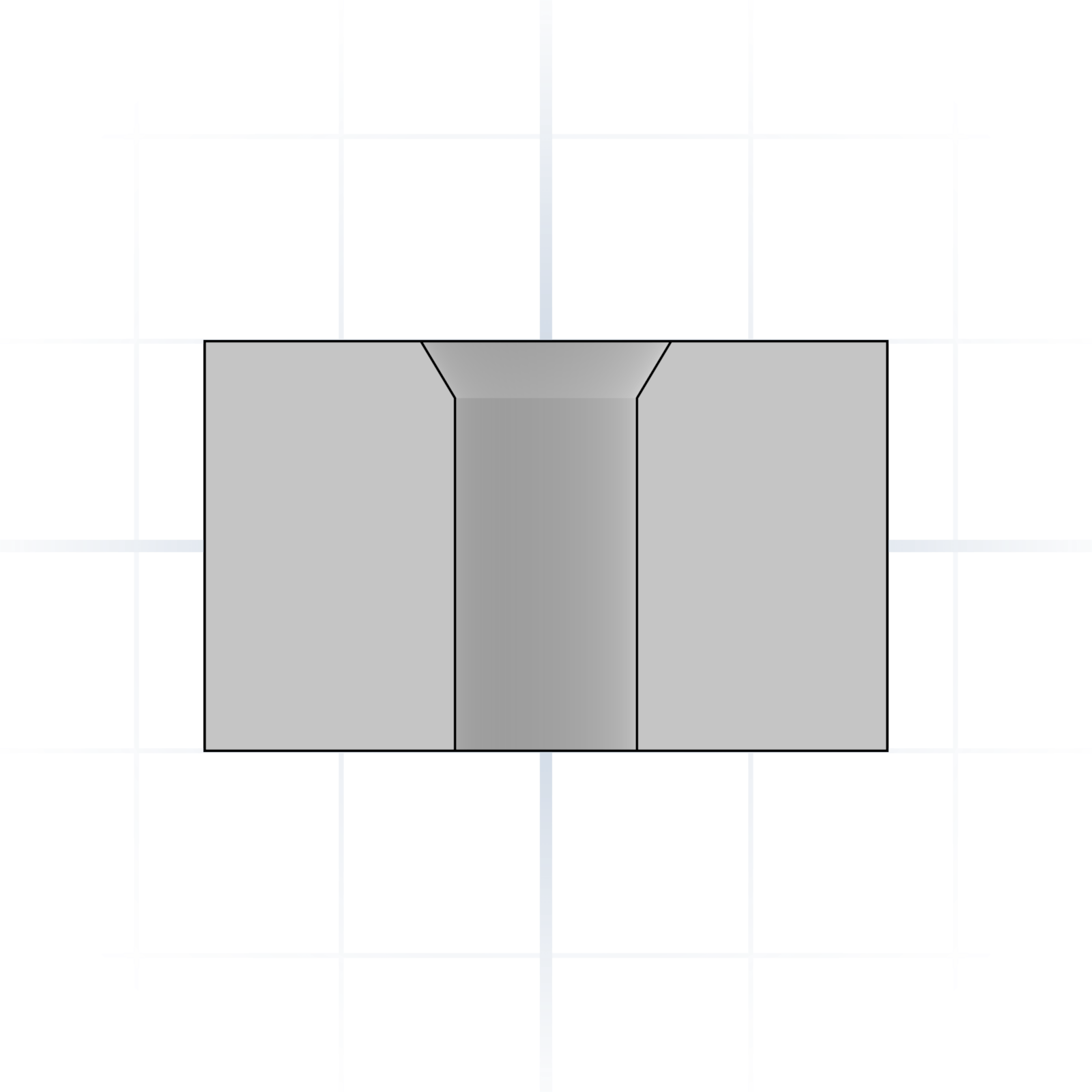
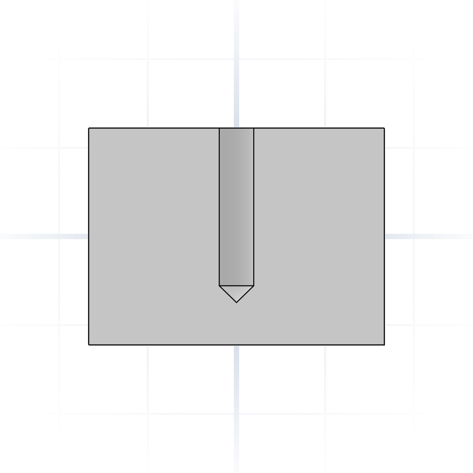
Need the hole size for a metric screw right now? Here it is. This chart covers the three holes you actually drill or model: the clearance hole (for a bolt to pass through), the tap drill (for cutting real threads with a steel tap), and the coarse thread pitch. The clearance columns are ISO 273 (close, normal, loose fits) and the tap drill sizes are the standard coarse-thread values at roughly 75% thread engagement.
If you'd rather punch in a size and get the number instantly, the Thread & Tap Drill Calculator does exactly that. Otherwise, read the chart.
Size
Thread Ø (mm)
Coarse pitch (mm)
Tap drill (mm)
Clearance close
Clearance normal
Clearance loose
M2
2.0
0.40
1.60
2.2
2.4
2.6
M2.5
2.5
0.45
2.05
2.7
2.9
3.1
M3
3.0
0.50
2.50
3.2
3.4
3.6
M4
4.0
0.70
3.30
4.3
4.5
4.8
M5
5.0
0.80
4.20
5.3
5.5
5.8
M6
6.0
1.00
5.00
6.4
6.6
7.0
M8
8.0
1.25
6.80
8.4
9.0
10.0
M10
10.0
1.50
8.50
10.5
11.0
12.0
M12
12.0
1.75
10.20
13.0
13.5
14.5
The two holes you'll reach for most
The numbers only click once you can picture what they are for. Almost every screw hole you model is one of these two, and the only real difference is whether the hole is bigger or smaller than the screw.
Clearance hole: the bolt passes through
Wider than the screw, so the bolt slides straight through and tightens
against a nut or a threaded part on the far side. This is the clearance
column in the chart above. For an M3 bolt, model about 3.4 mm.
Pilot hole: the screw bites the plastic
Narrower than the screw, so the thread cuts its own grip as you drive it
in. Aim for roughly 0.75 to 0.8 times the screw diameter. For an M3
screw, that is about a 2.4 mm hole.
For anything you take apart more than once, or that carries real load, there is a third option: the heat-set brass insert, which gets its own section further down.
Which column do I actually use?
Those numbers come straight off a machinist's chart, and they assume a metal part cut with a drill and a tap. On a 3D printer, the rules bend. Here's the short version of what to reach for.
For a bolt to pass through a printed part, start from the normal or loose clearance column, not the close one. FDM holes come out undersized (more on that below), so a "close fit" at nominal size will usually bind on the threads. Give it a little extra room. Here is that normal-fit column plotted across the whole range, so you can see how the hole grows with the screw.
Normal-fit clearance hole diameter from M2 to M12, bar lengths drawn in proportion. This is the column to start from when you want a bolt to pass through a printed part.
For threads that need to hold, don't tap plastic if you can avoid it. Printed threads and plastic-tapped threads strip after a few cycles. Use heat-set brass inserts instead. They're the robust, reusable option and they're worth the small upfront cost.
For actually running a steel tap into metal (or, occasionally, into a solid printed boss you only assemble once), that's what the tap-drill column is for. Drill that size, then cut the thread.
Why FDM holes print undersized
This trips up everyone at least once. You model a 3.4 mm hole for an M3 bolt, print it, and the bolt won't go in. The hole measures more like 3.1 or 3.2 mm.
Two things are working against you. The nozzle over-extrudes slightly on the inside of curves, so the plastic creeps inward on a hole. And the part shrinks a touch as it cools. Horizontal holes (printed on their side, hole axis parallel to the bed) are worse still, because the top of the hole sags and the whole thing goes a bit oval.
You've got three ways to deal with it:
Model the hole about 0.2 to 0.4 mm oversize on diameter. Lean toward the higher end for small holes, and add roughly another 0.1 mm if the hole prints horizontally.
Drill or ream the hole to size after printing. Model it slightly undersize and clean it up with a bit.
Use your slicer's XY hole or contour compensation, which nudges the toolpath outward on inner perimeters so holes come out closer to nominal.
None of these is "right." They're all fine. Pick the one that fits your workflow and, ideally, print a quick test.
Self-tapping a screw straight into plastic
Sometimes you just want to drive a screw into a printed boss and be done with it. That works, within reason, if you size the pilot hole correctly.
Aim for a pilot hole diameter around 0.75 to 0.80 times the screw's major diameter. For an M3 screw that's roughly a 2.3 to 2.4 mm hole. Make the boss around 2 to 2.4 times the screw diameter across, and give the screw about 2 to 2.5 diameters of engagement depth so there's enough material to bite into. Then print a test boss before you commit it to the real part.
Heat-set inserts (the option I'd pick)
If the joint gets taken apart more than once, or it carries any real load, put a brass heat-set insert in it. You melt it into an oversize hole with a soldering iron, and you get a proper metal thread that doesn't strip.
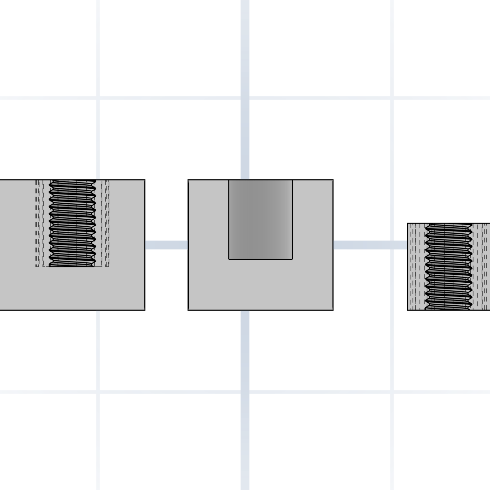
How it goes together: print a plain pocket (center), melt the brass insert
(right) into it with a soldering iron, and you are left with a durable metal
thread (left). Size the pocket to the insert's datasheet, not to the screw.
The catch: the modeled hole diameter depends on the specific insert. Different manufacturers spec different holes for the "same" size insert. As a starting point:
Insert size
Typical modeled hole Ø (mm)
M2
3.0–3.2
M2.5
3.4–3.6
M3
4.0
M4
5.6
M5
6.4
Treat those as a rough guide, not gospel. Always check the datasheet for the inserts you actually bought, and if you want to go deeper on how those datasheet numbers can be off, CNC Kitchen has a good writeup (linked below).
Getting the fit right on printed parts
Clearance holes are only half the story. If you're fitting two printed parts together (a peg in a hole, a lid on a box), the gap between them matters just as much as the hole for a bolt. That's a separate topic with its own numbers, and I've collected them in the 3D printing tolerances and clearances guide. If you're building anything that assembles, read that next.
For the printer-tuning side of things (flow, E-steps, shrinkage compensation), the free 3D printing tools collection has calculators for most of it.
Let GrandpaCAD size the holes for you
Memorizing these numbers is the old way. With GrandpaCAD you just describe the part ("a bracket with two M3 clearance holes and a heat-set insert boss for M4") and it generates the CAD with the right holes already sized. You can tell it the fit you want and it does the math.