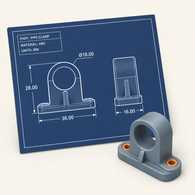
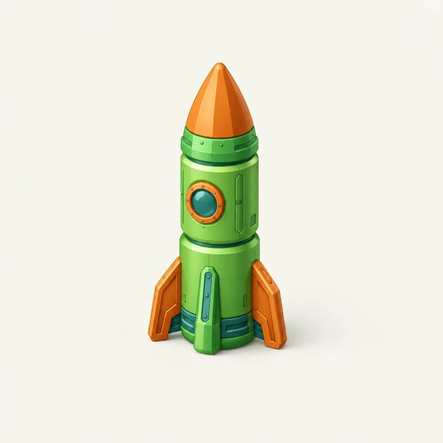
Chapter07 / 36
Chapter 2
The vocabulary
The basic shapes and operations of a parametric part. You build even the most complex model by using these words in the right order.
Preview: this cheatsheet is still in development and the content hasn't been independently verified.
The basic shapes and operations of a parametric part. You build even the most complex model by using these words in the right order.
The starting shapes for almost any design. Every complex part begins as one or two of these.
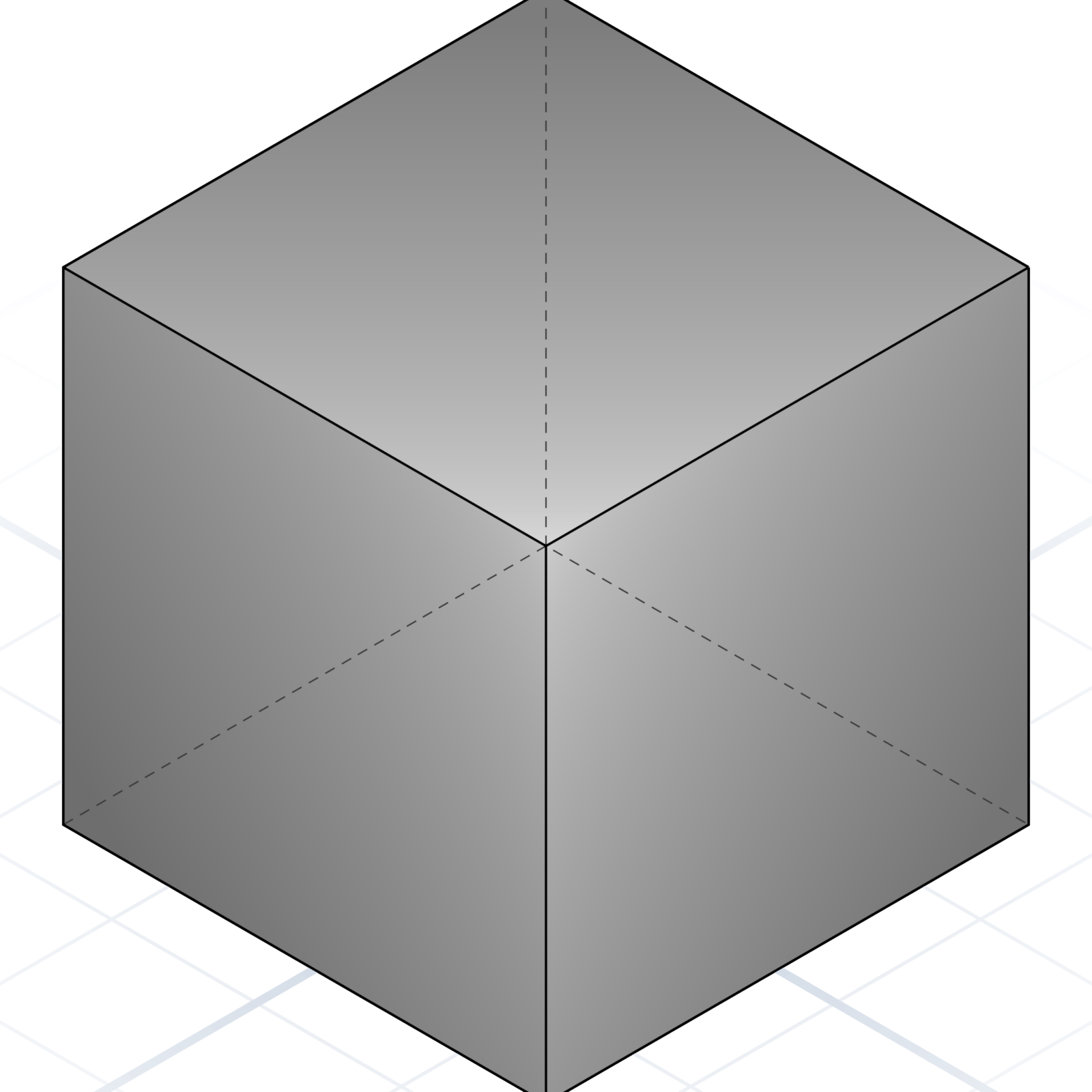
A six-sided block. Width, depth, height in millimetres.
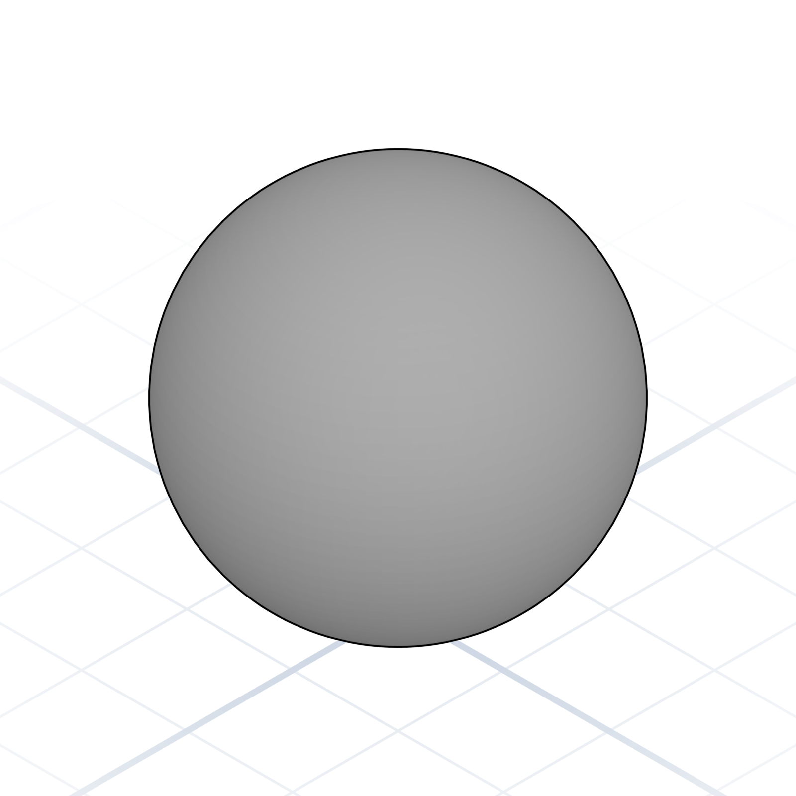
A ball. Specify radius or diameter, not both.
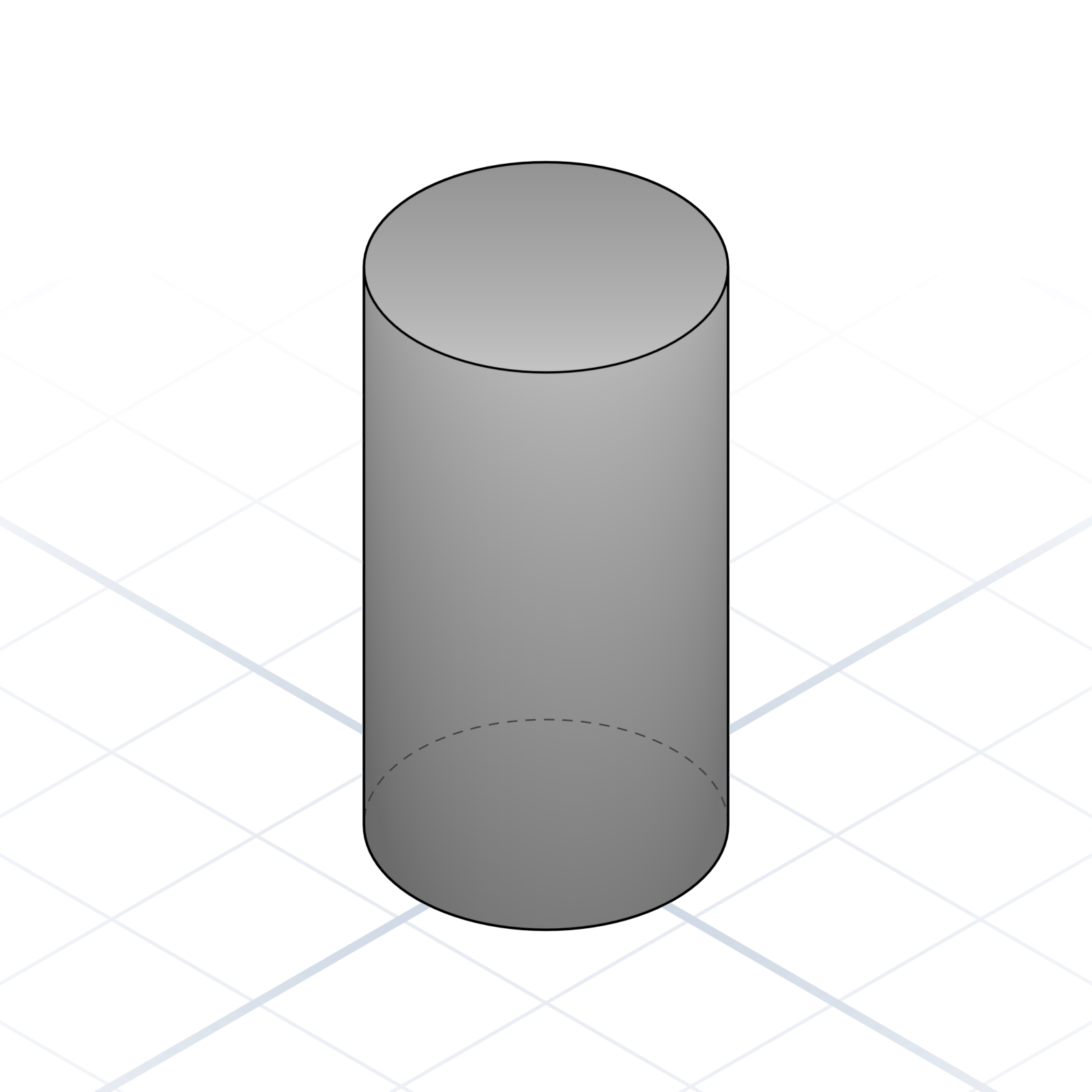
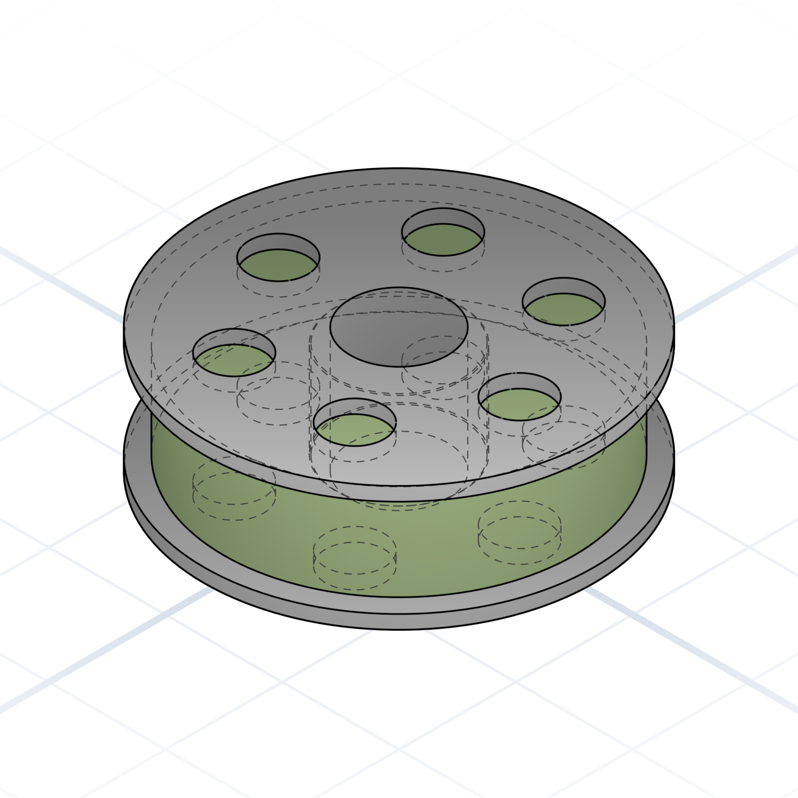
A tube or rod. Say “tube” if you want it hollow.
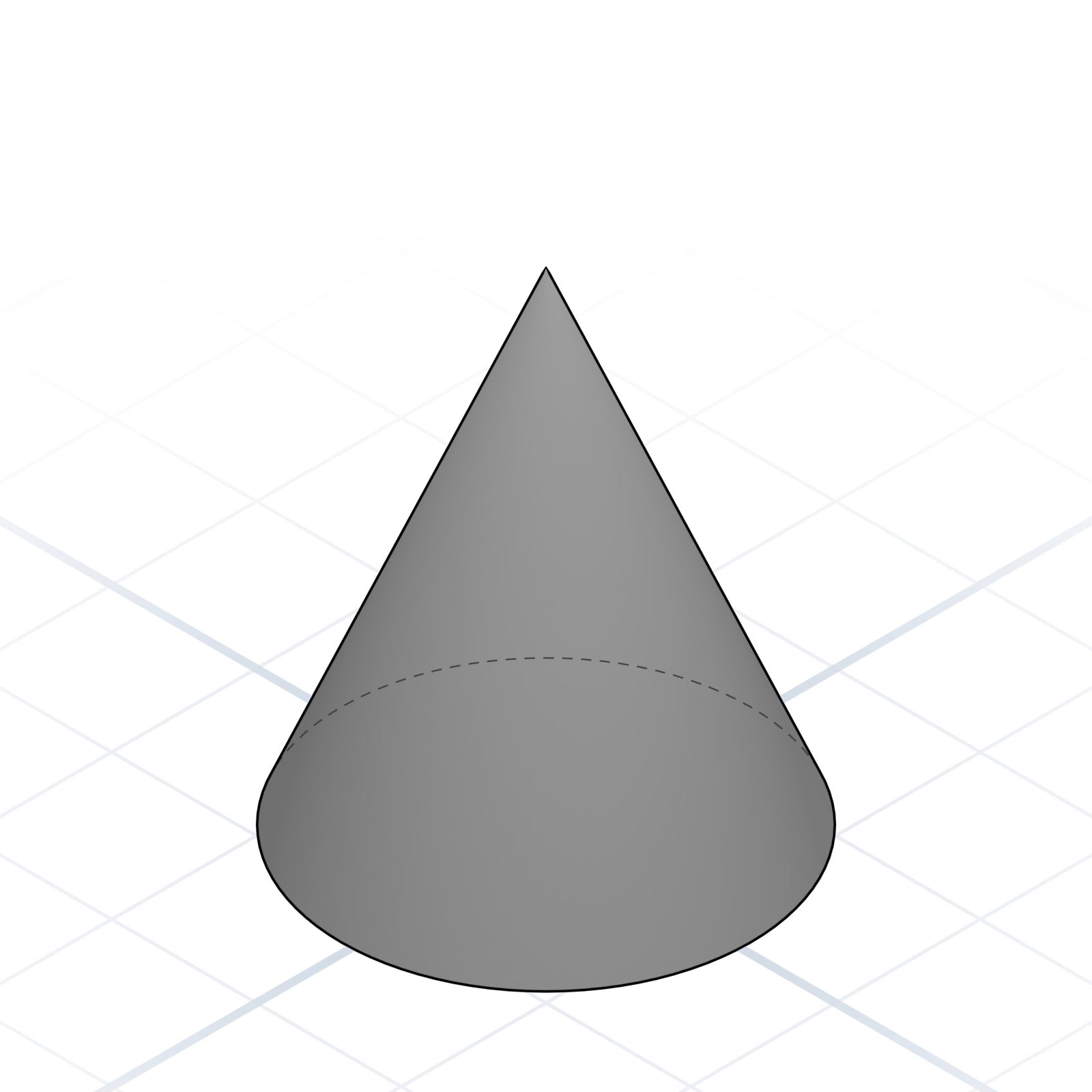
Tapers from a circle to a point. Say “truncated” to end it in a smaller circle instead of a point.
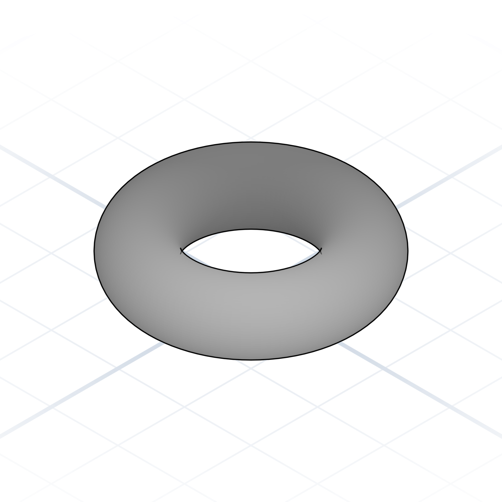
A donut. Give the ring radius and the tube radius.
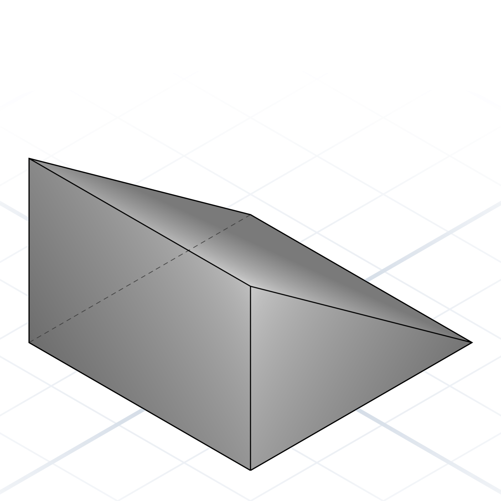
A triangular prism. Ramps, brackets, and gussets start here.
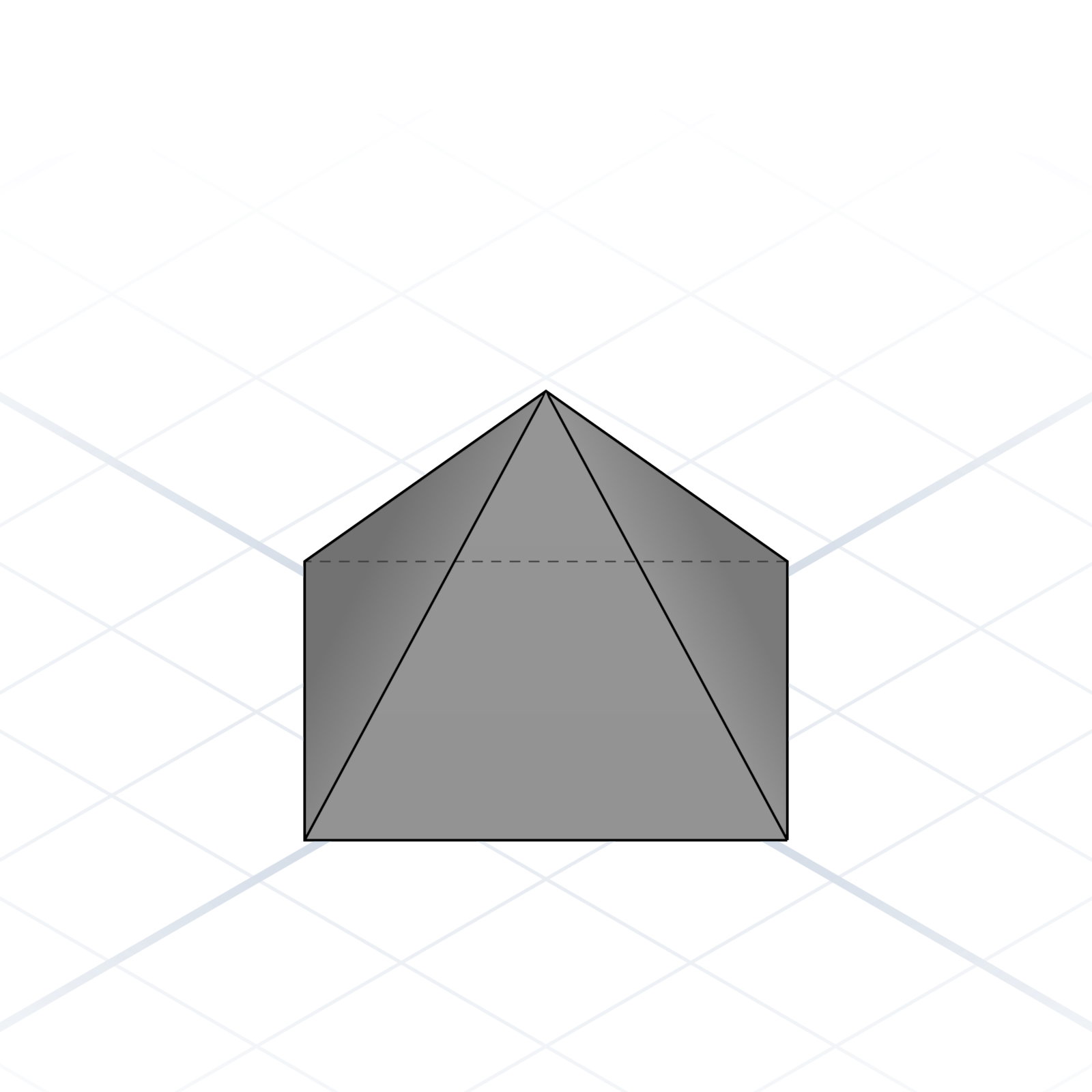
Tapers from a polygon to a point. Square base by default, but it can have any number of sides.
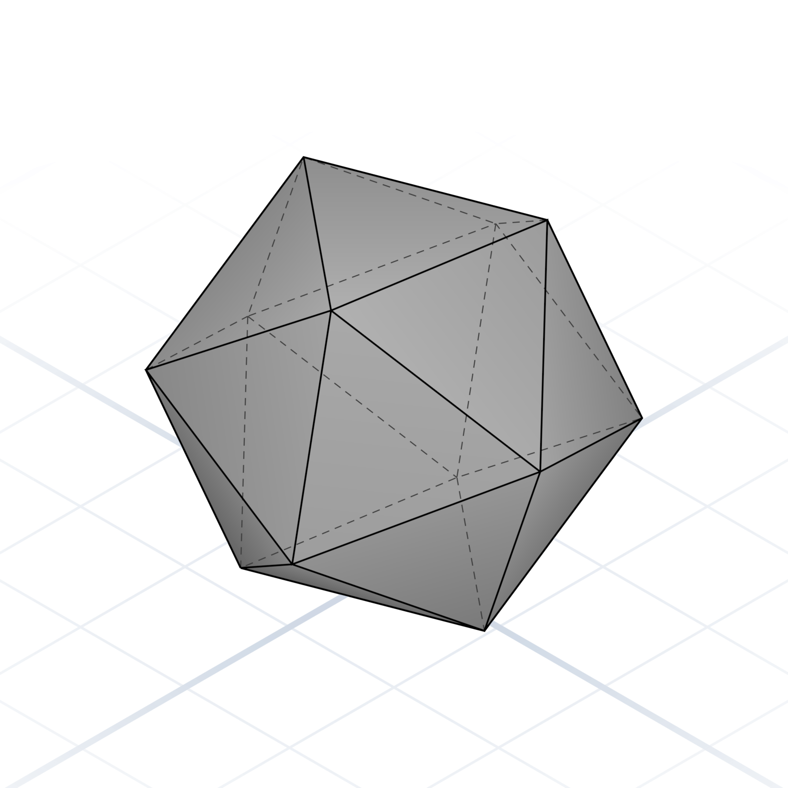
A custom mesh from points and faces. Last resort when nothing else fits.
The basic shapes and operations of a parametric part. You build even the most complex model by using these words in the right order.

36 printed pages of the AI CAD vocabulary you actually need. Bound, ready to flip through next to your keyboard.
One email when it ships. No spam, ever.
 A pocket reference
Plain words for asking AI to build the parts you want, the right way on the first try.
Every craft has its words. Tell a carpenter rabbet and they know the cut, the tool, and the fit before you finish the sentence. The right word does the explaining for you.
AI is the same. Ask for “a thingy with a hole” and you get a shrug in 3D. Ask for “an M3 counterbore on a 5 mm wall” and you get a part. This little book is the words.
How a session flows: describe, look, correct.
Shapes and operations: the moves every model is made of.
Features, holes, fits, and the hardware to design around.
Images, colour, and models that adjust themselves.
Filament, export, slicing, printing.
For Grandpa Franc, who built me things.
You describe, GrandpaCAD builds, you look and correct. This chapter is the rhythm of a working session.
One part, start to finish. This is the whole loop.
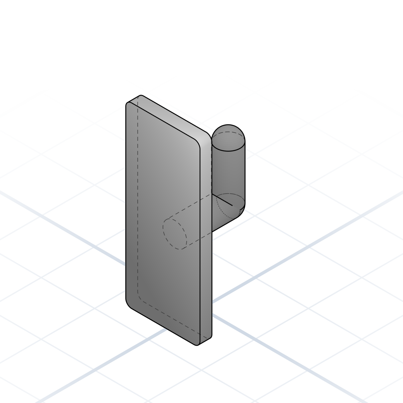
“A wall hook for the workshop. Base plate 60 × 25 × 4 mm, one hook in the middle.” Size and purpose are enough to start. You don’t need every detail.
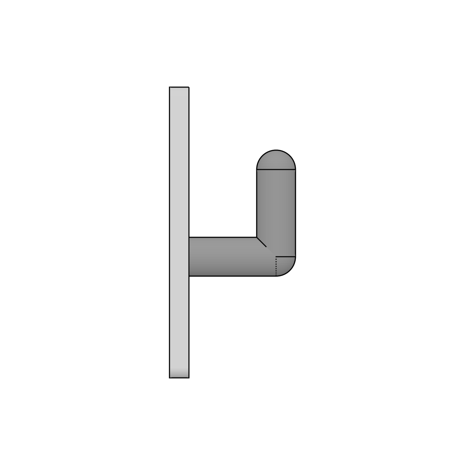
The model appears. Check how the parts fit together, the proportions, and the details.
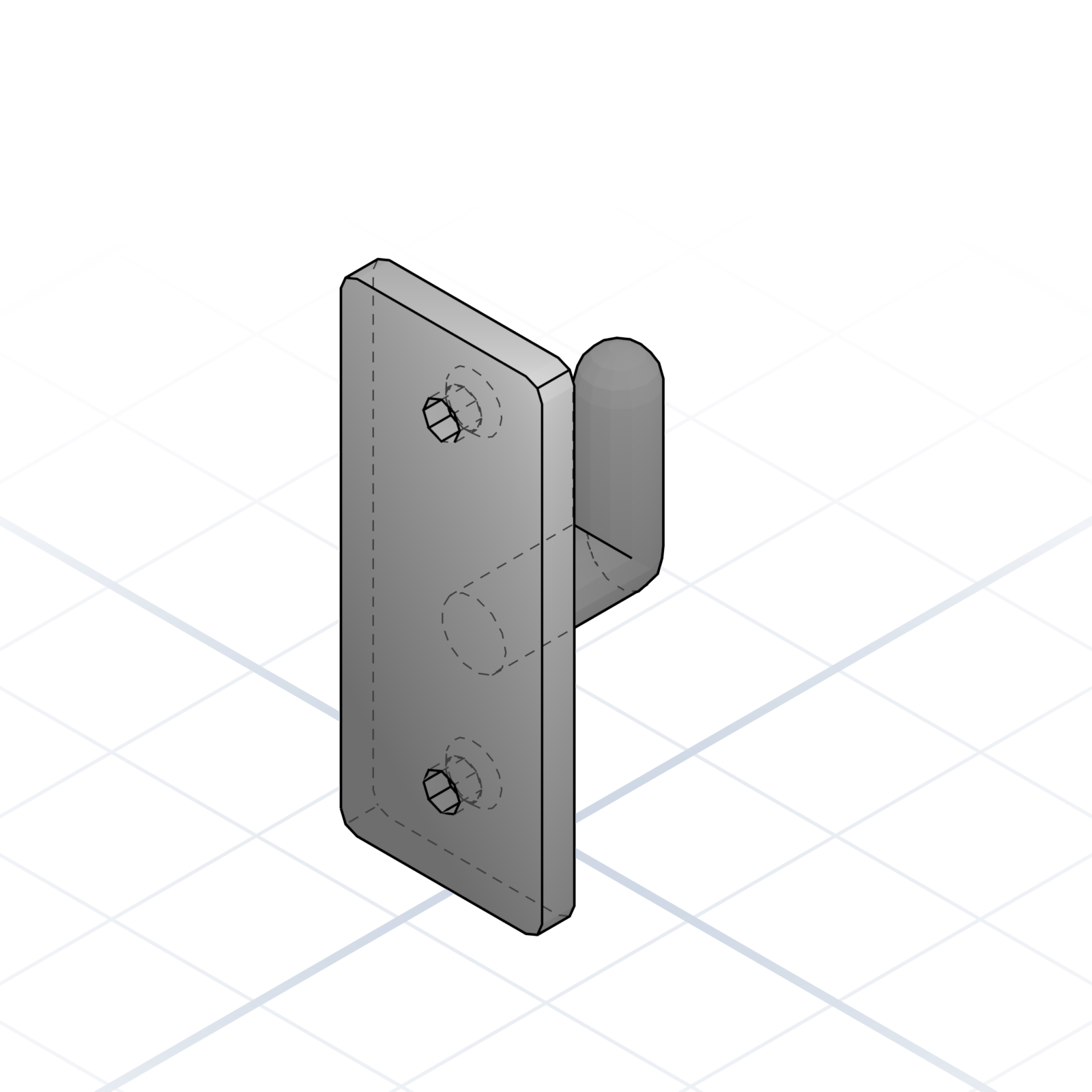
“Add two countersunk holes for M4 screws, 40 mm apart.” One correction per message; the rest stays as it was.
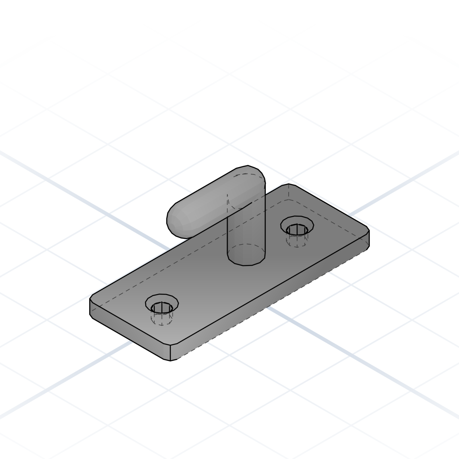
Download it. Printing is covered in chapter 5.
Complex parts come out cleaner when you give the AI a plan, not a paragraph.
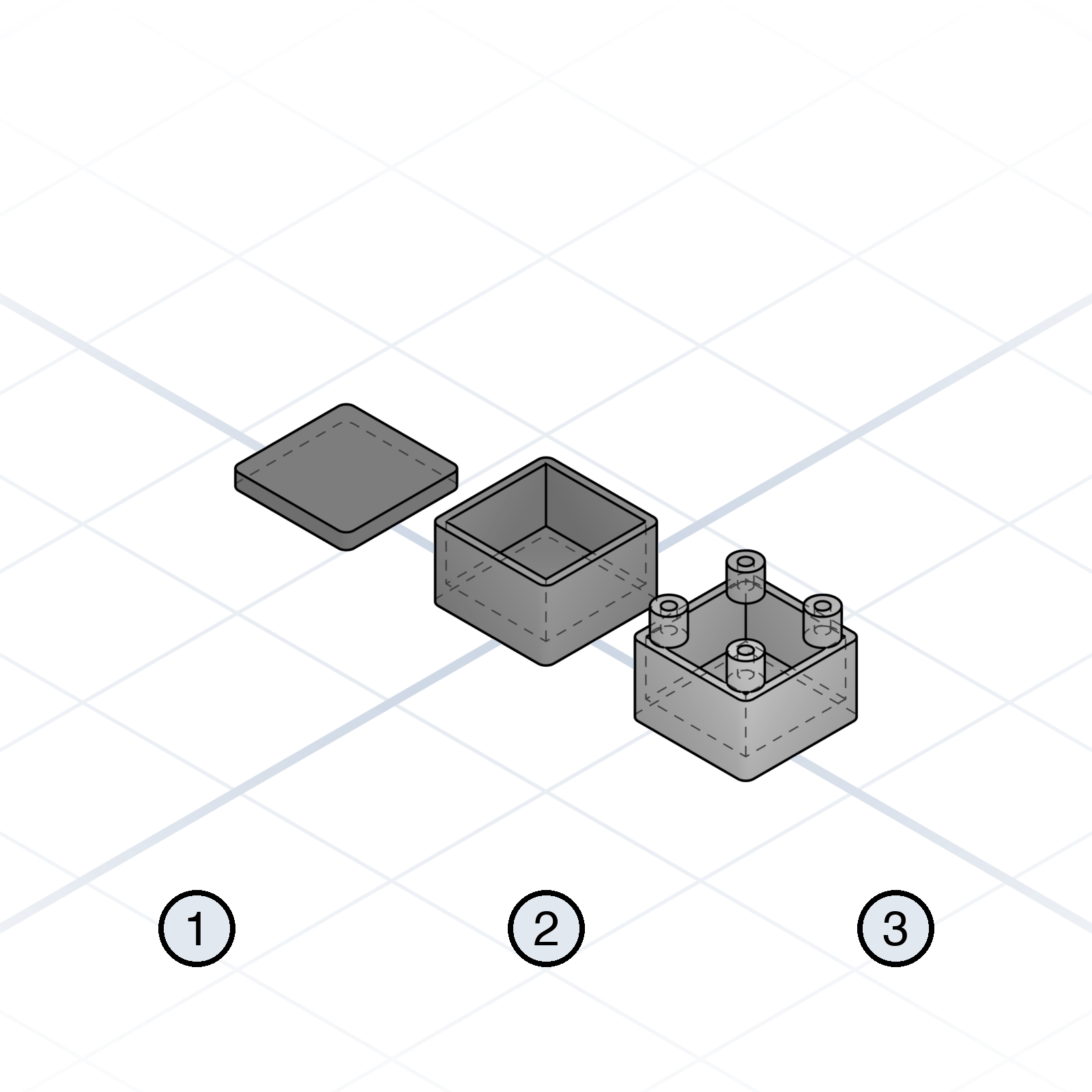
“First the base, then the walls, then four mounting bosses.” Order is information.
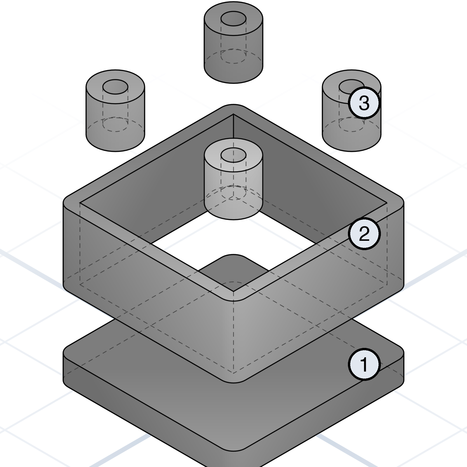
Named parts give you something to mention when you iterate.
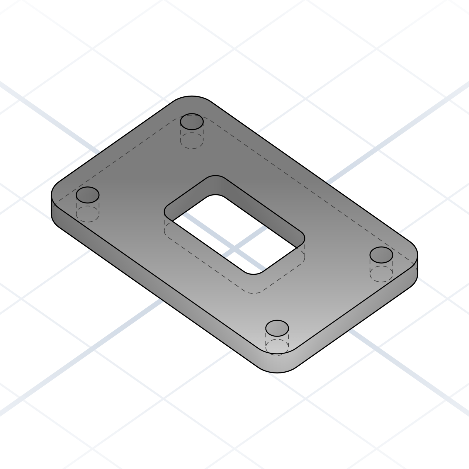
Get the silhouette right before adding details. Features attach to a stable foundation.
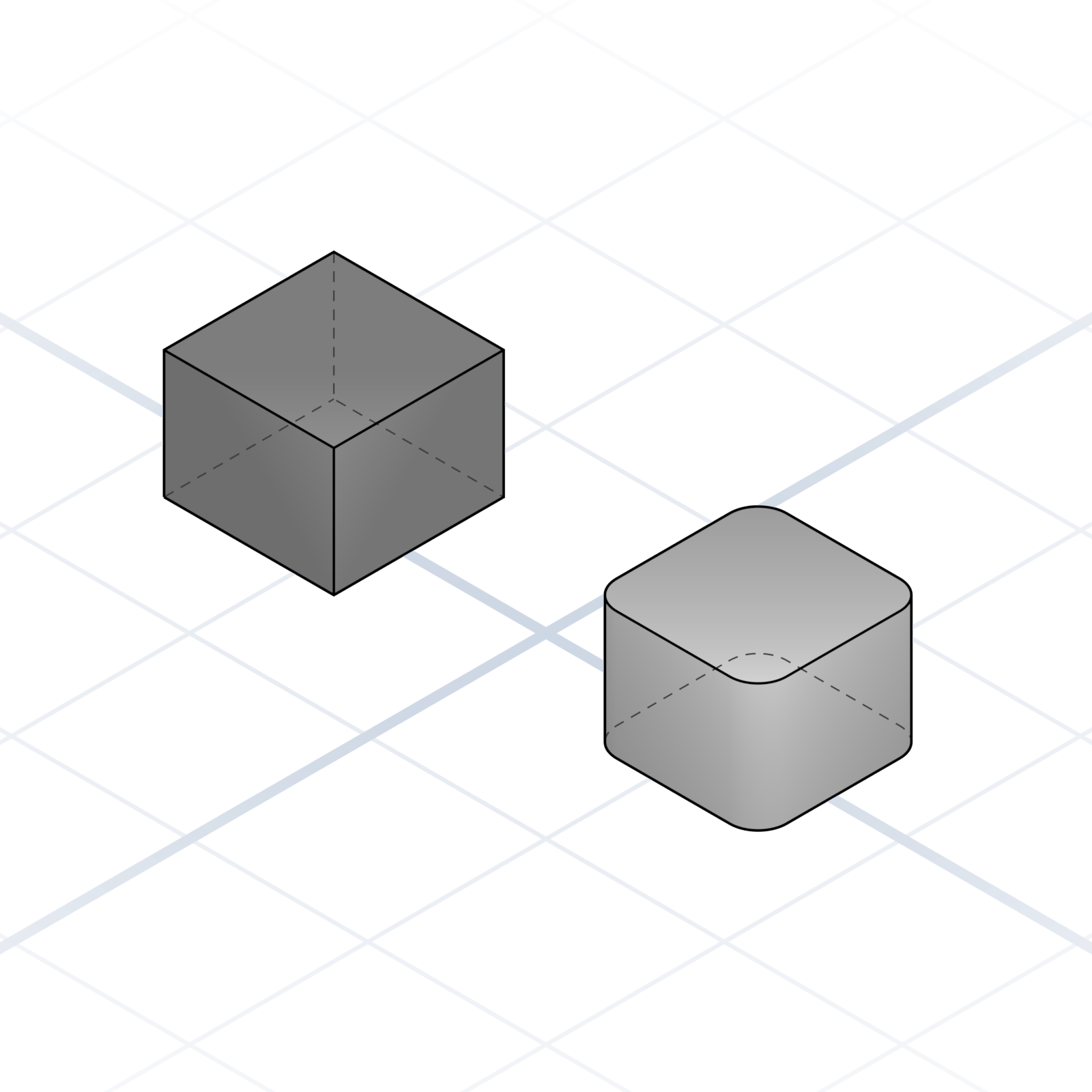
Fillets, chamfers. Cheap to add and cheap to take away.
Numbers without context are guesses. Pin them down up front.
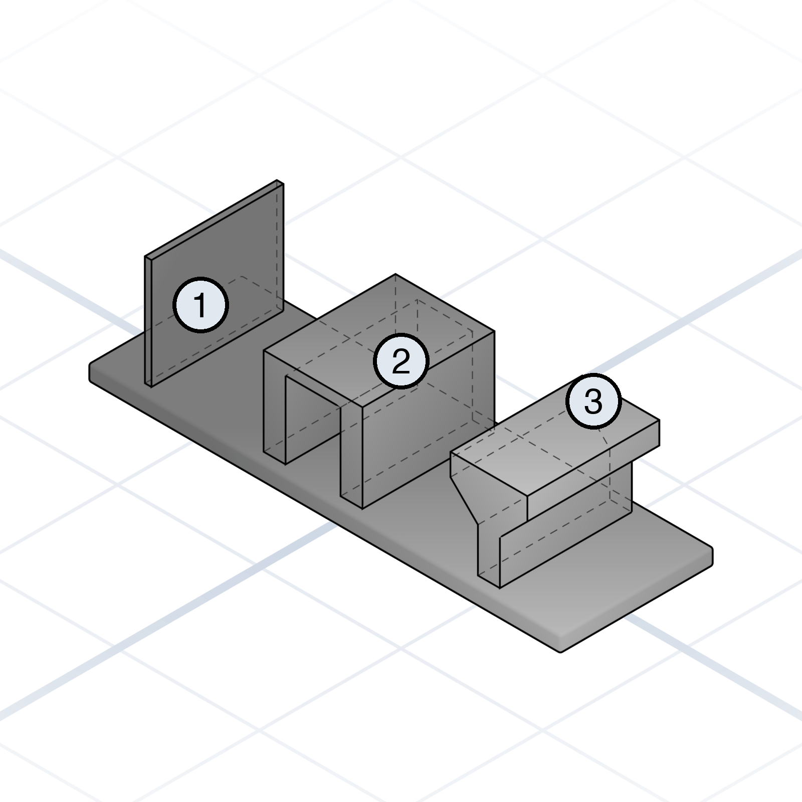
Walls should be at least 1.2 mm, or they crack. Short bridges print cleanly; past about 10 mm they start to sag. Surfaces leaning up to 45° from vertical print without supports.
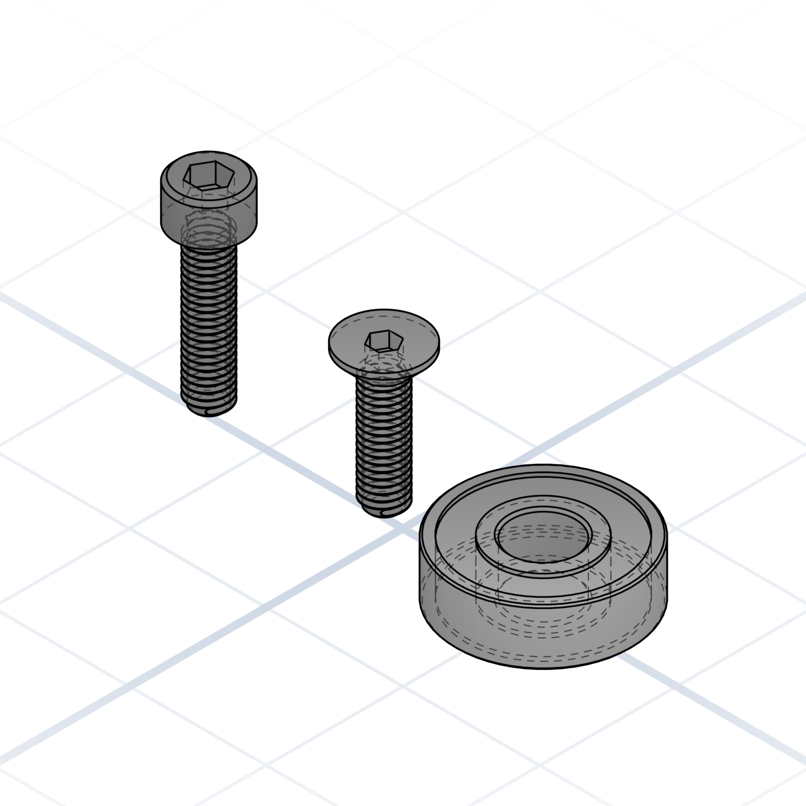
“M5 cap screw”, “M5 countersunk”, “608 bearing”. The standard name already carries every dimension, so you don’t have to spell them out.
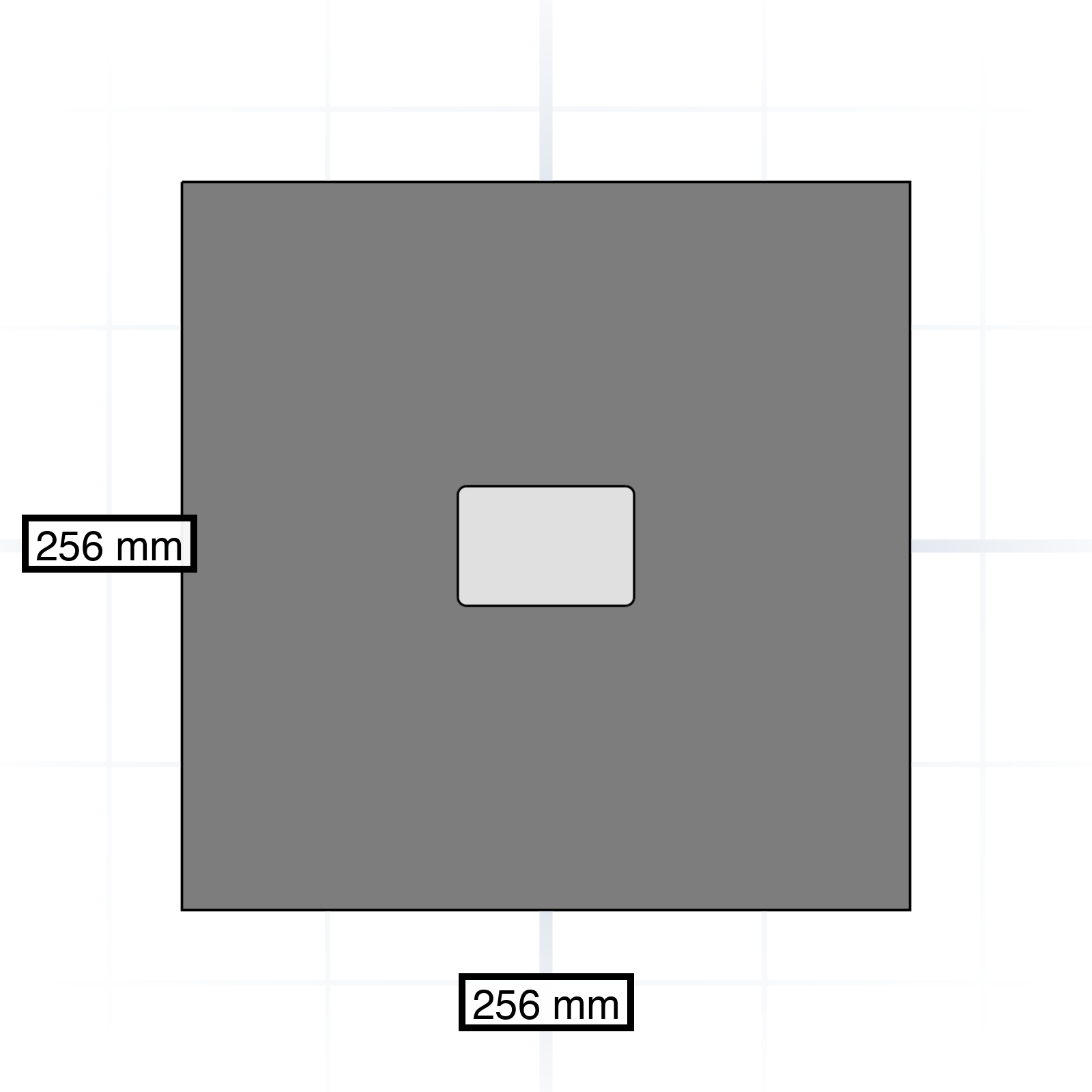
“Fits a 256 × 256 mm bed.” A stated build plate stops the model from drifting to absurd sizes.
Where something sits is half the description. Anchor every part to something concrete.
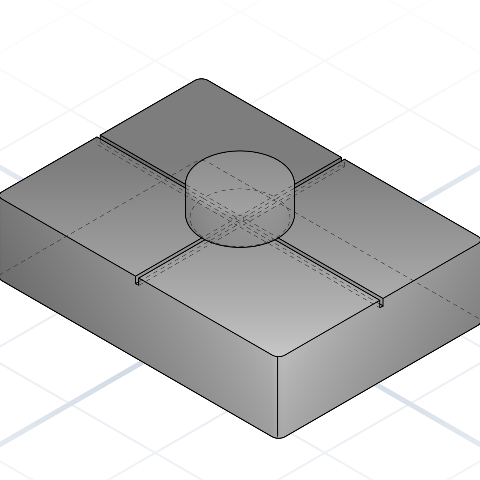
“Centred on the top face” is unambiguous. “Near the top” is not.
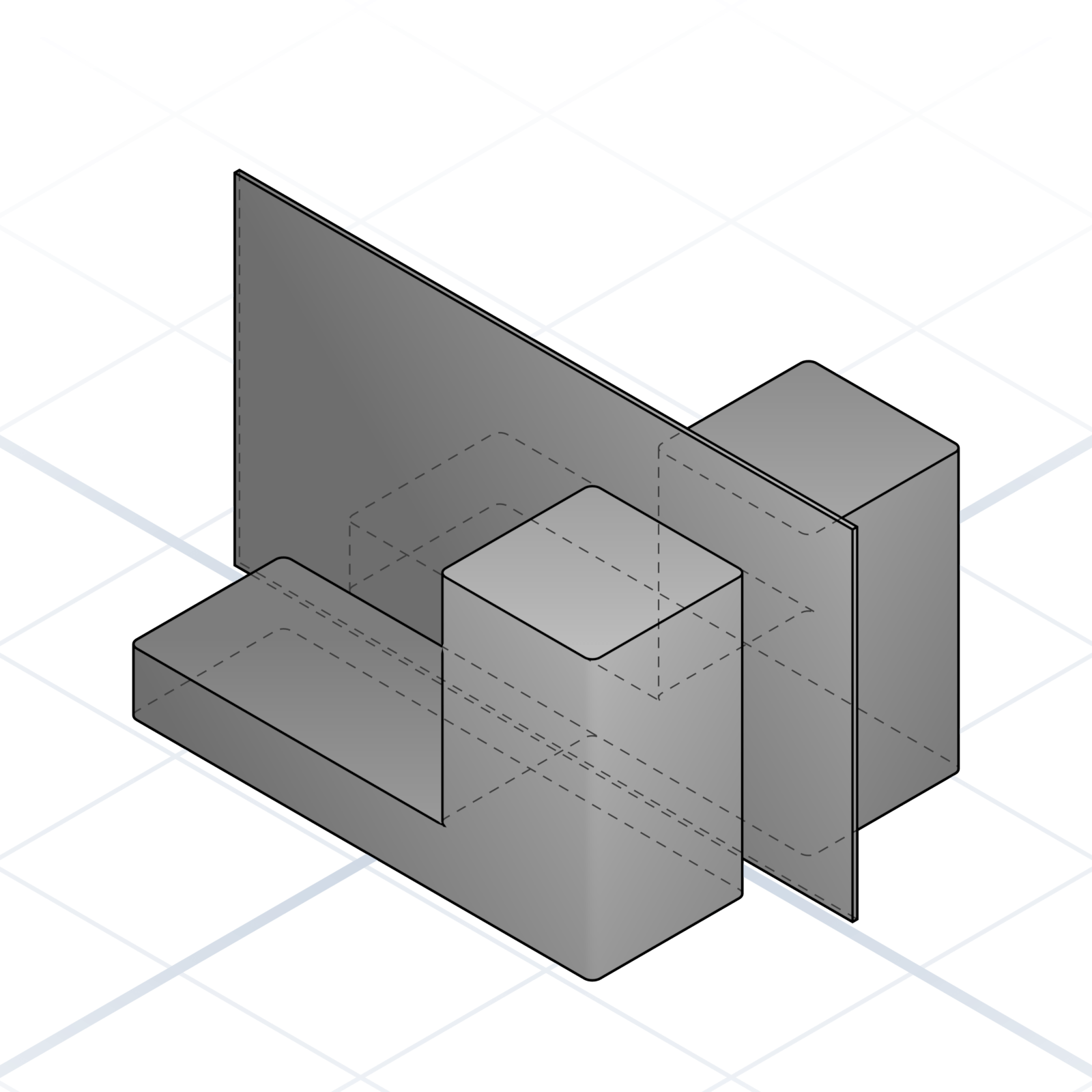
“Mirror across the centre” gives the AI a fixed point to anchor every measurement to.
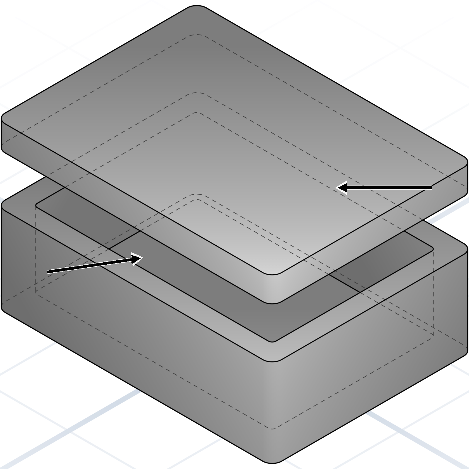
Name which face touches what. “The lid sits on the rim of the box, not inside it.”
The first generation is rarely the final one. Be exact about what is wrong, because the problem is usually easier to describe than the fix.
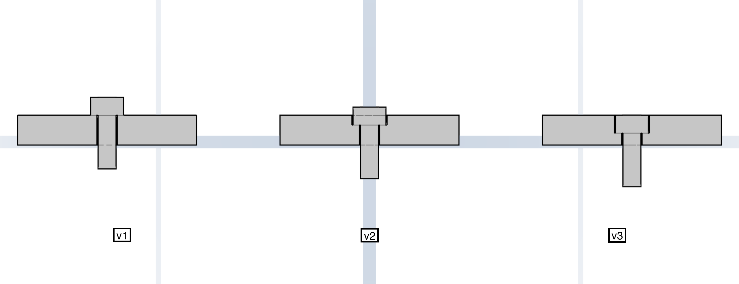
“The screws stick out 1 mm” tells the AI what to solve. Let it find the right way to fix it.
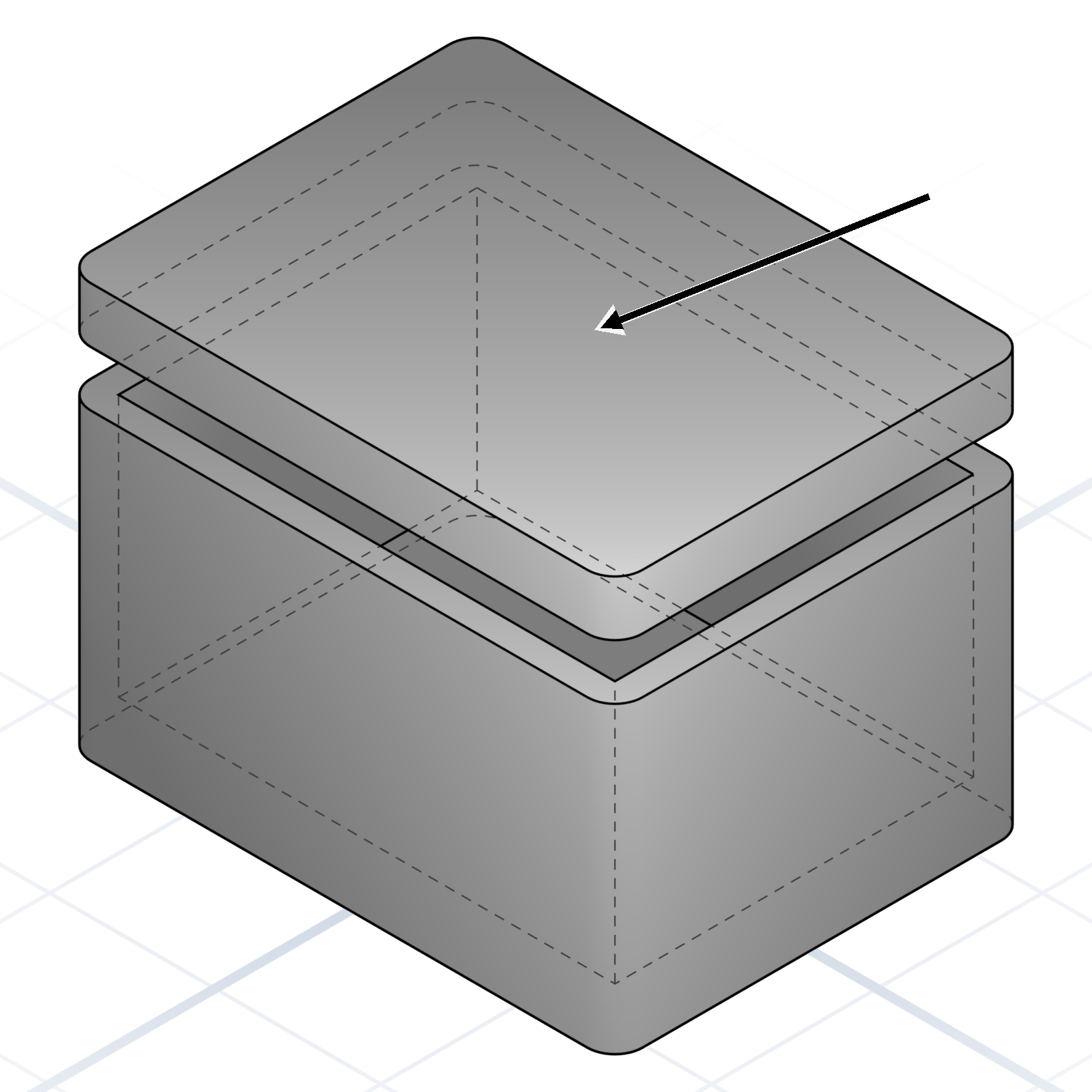
“Make the lid 2 mm thicker” lands. “Make it sturdier” wanders.
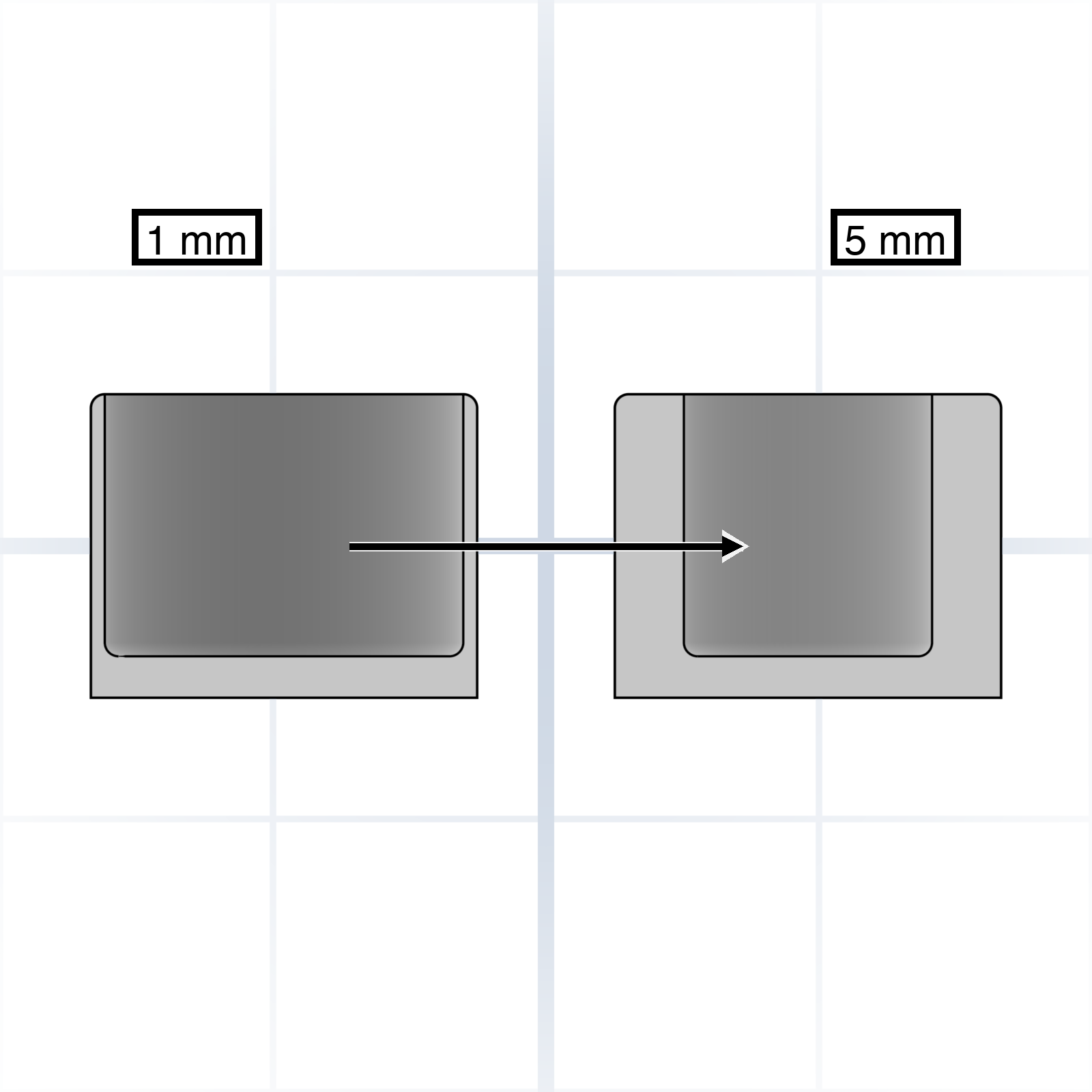
“Change wall thickness from 1 to 5 mm” leaves no room for interpretation.
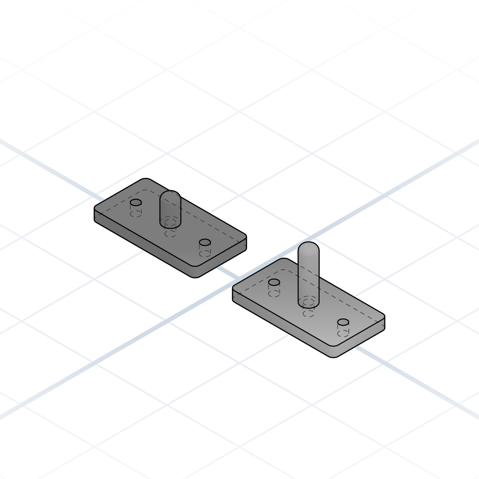
“Keep the hole pattern as is” prevents a full redesign on every iteration.
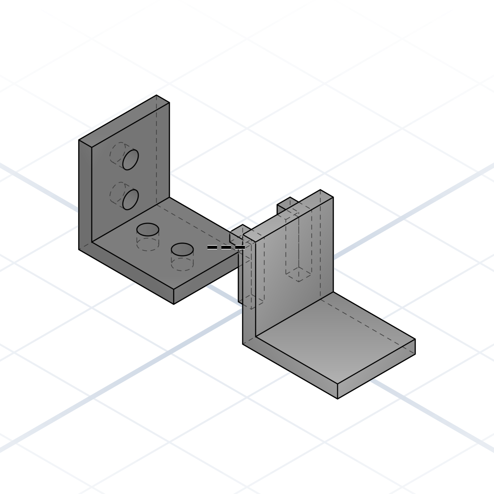
When the AI keeps repeating the same mistake, ask it to take a completely different approach. That makes it start fresh.
The basic shapes and operations of a parametric part. You build even the most complex model by using these words in the right order.
The starting shapes for almost any design. Every complex part begins as one or two of these.
A six-sided block. Width, depth, height in millimetres.
A ball. Specify radius or diameter, not both.
A tube or rod. Say “tube” if you want it hollow.
Tapers from a circle to a point. Say “truncated” to end it in a smaller circle instead of a point.
A donut. Give the ring radius and the tube radius.
A triangular prism. Ramps, brackets, and gussets start here.
Tapers from a polygon to a point. Square base by default, but it can have any number of sides.
A custom mesh from points and faces. Last resort when nothing else fits.
How to move, turn, and reshape something that already exists. Order matters: rotate then move is not the same as move then rotate.
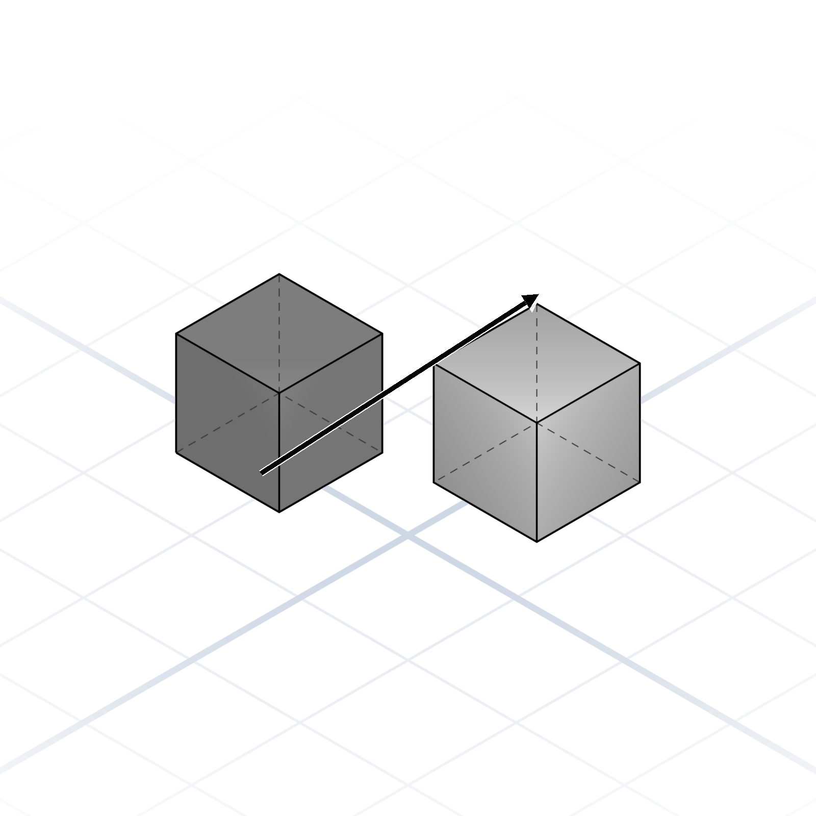
Move along X (left/right), Y (front/back), or Z (up/down).
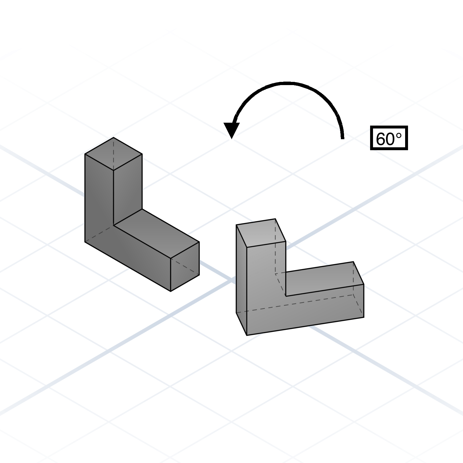
Spin around an axis you name, e.g. “rotate around X”. Give the angle in degrees.
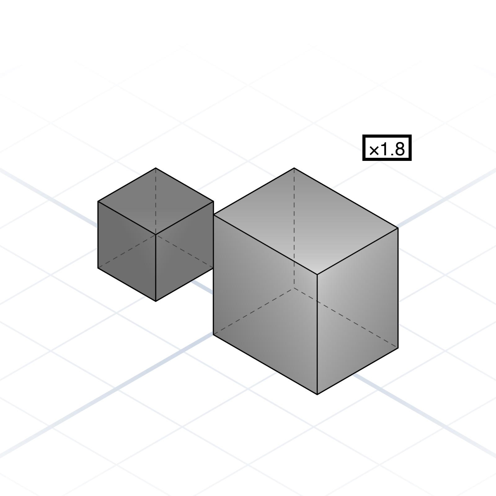
Resize it, either evenly in all directions or along a single axis. Along one axis only, a sphere becomes a stretched ellipsoid.
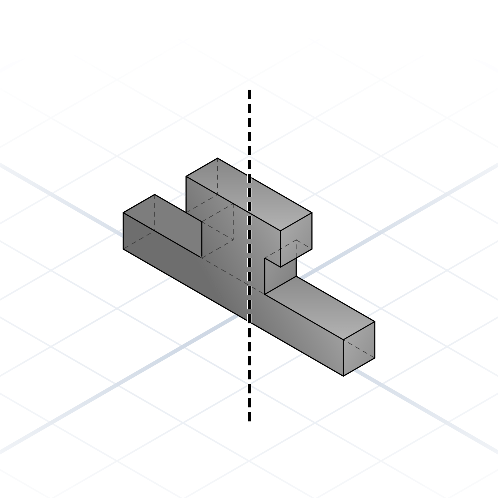
Reflect across a plane. Good for symmetric parts.
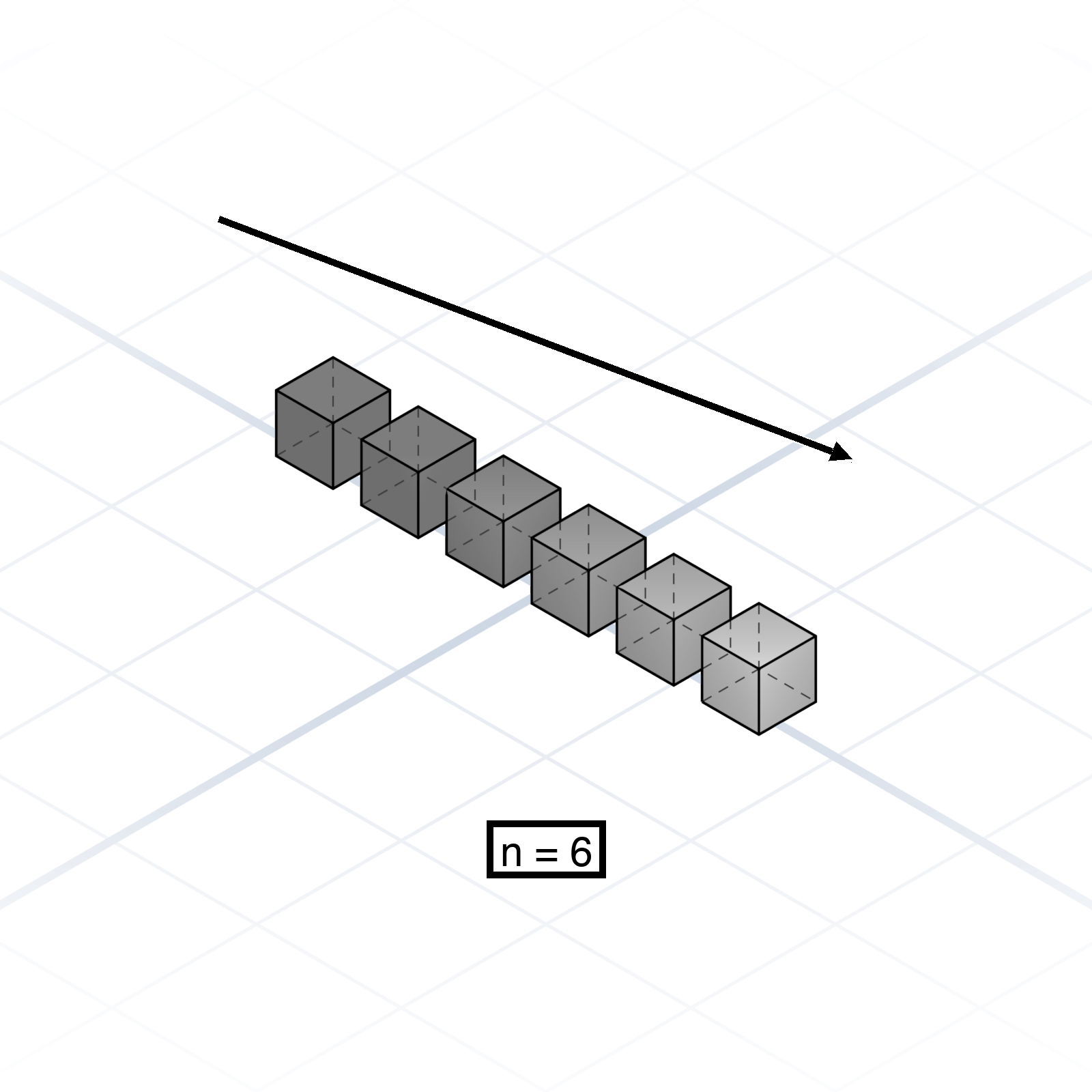
Duplicate in a straight line. Give the count and the spacing.
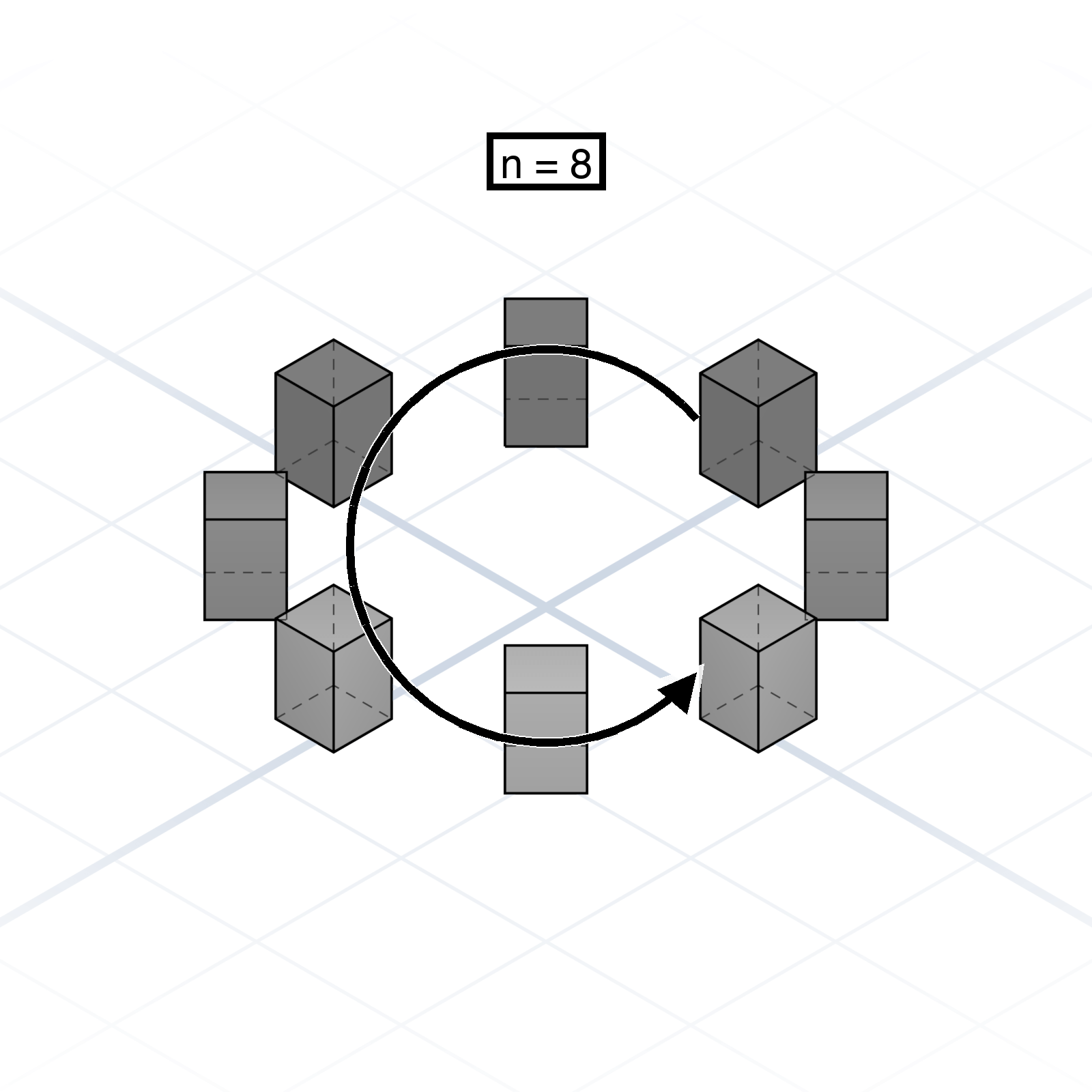
Duplicate around an axis. Give the count, plus a full sweep angle or a radius and spacing.
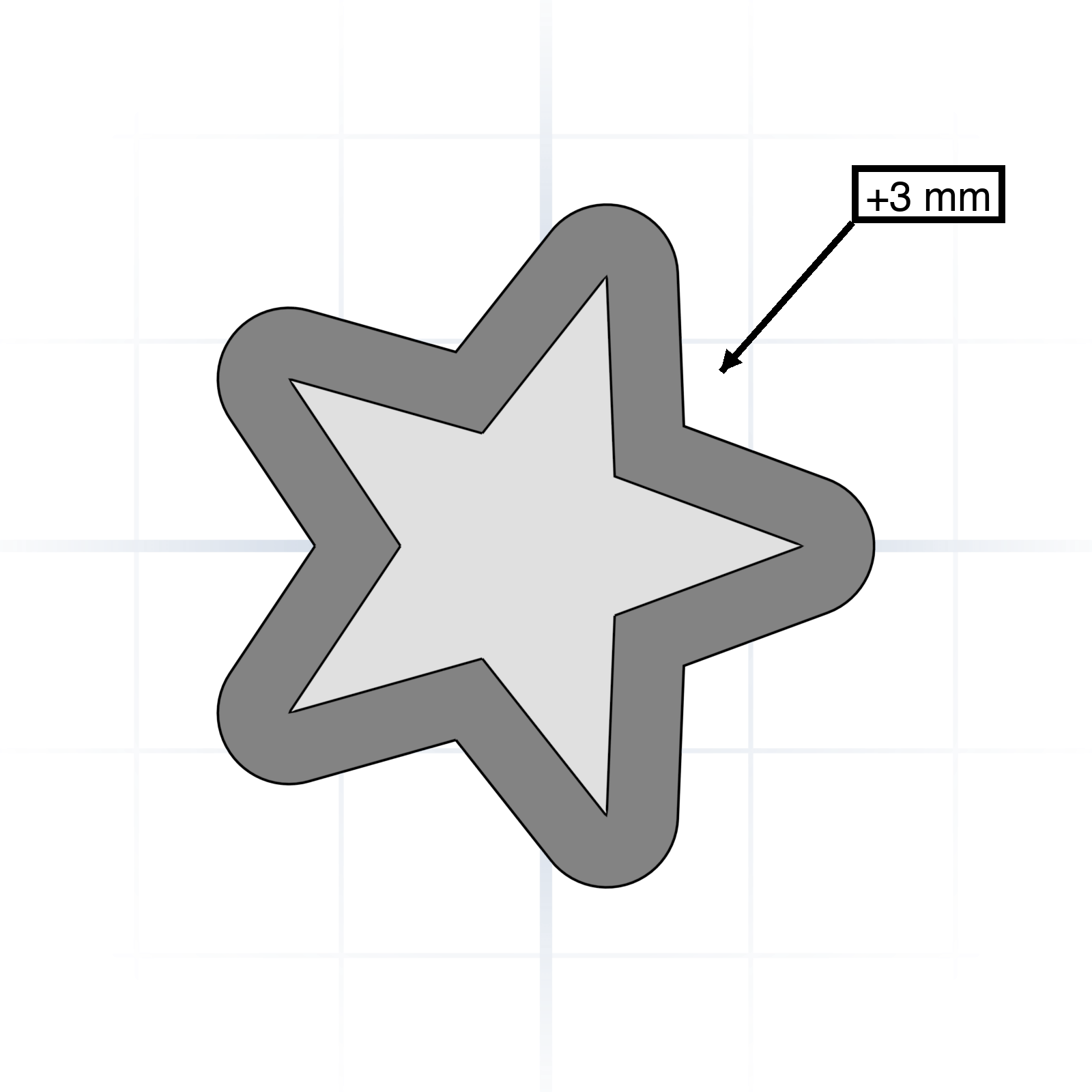
Grow or shrink a shape by a fixed distance on every side. Inflates or deflates a profile in place.
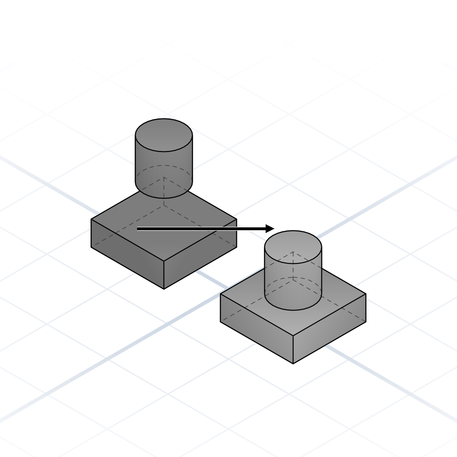
Snap one face, edge, or corner to another. “Align the lid flush with the rim of the box.”
Combine simple shapes into complex ones; most parametric models are booleans all the way down. All four examples below start from the same cube and sphere.
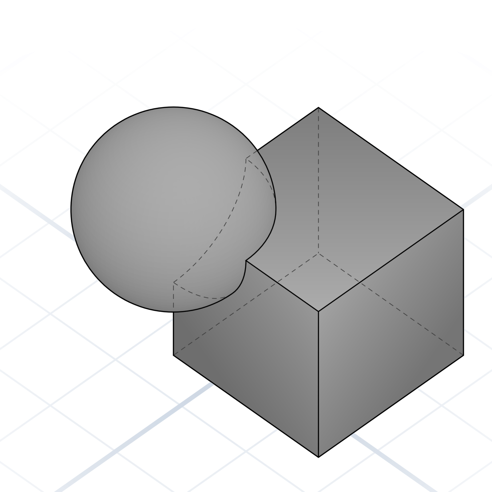
Fuse two shapes together. They become one new part.
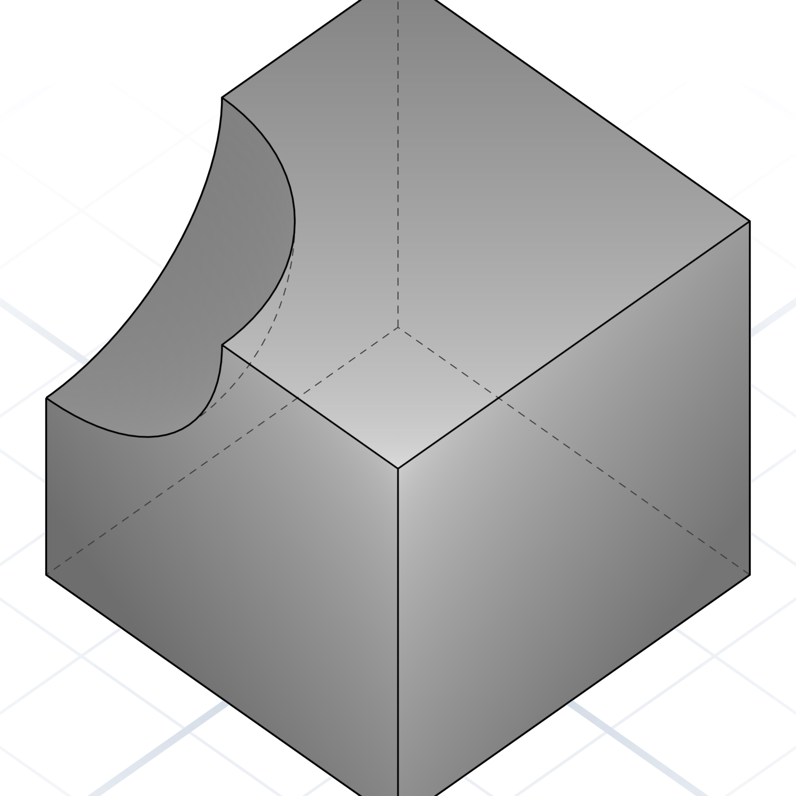
Subtract one part from another. The way you make holes and cutouts.
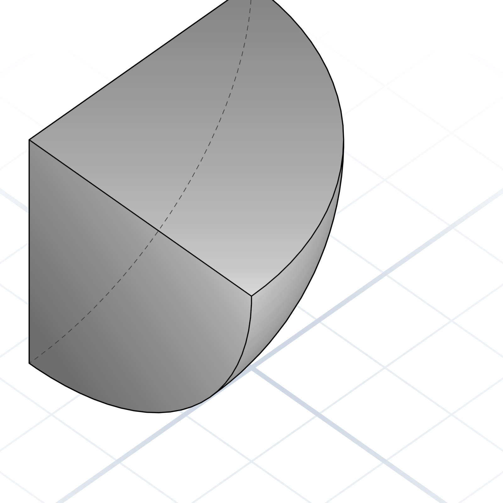
Keep only the overlapping volume. Useful for trimming to a bounding shape.
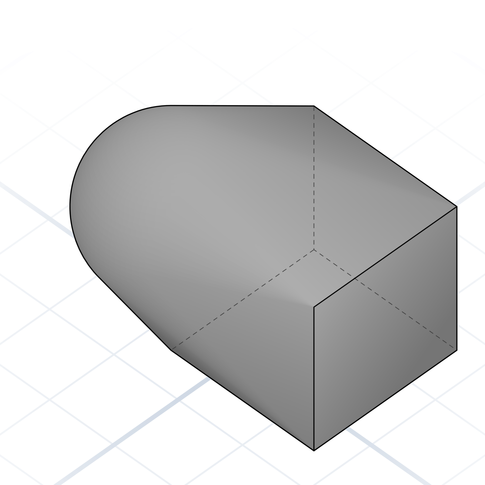
Wrap a tight “skin” around a set of shapes.
Detail operations. These are what make a part look intentional instead of blocky.
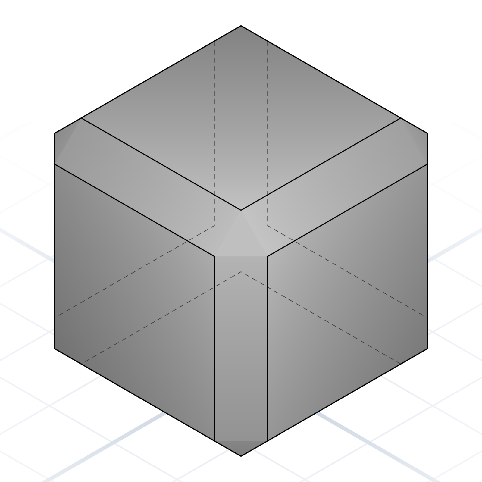
A flat cut on an edge, usually 45°. Eases insertion and breaks sharp corners.
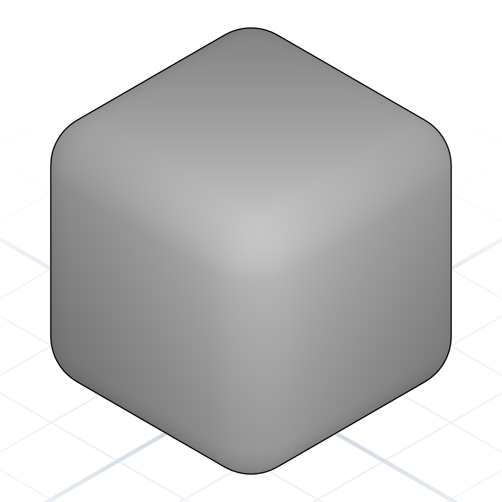
A rounded edge. Stronger than a sharp corner, friendlier to touch.
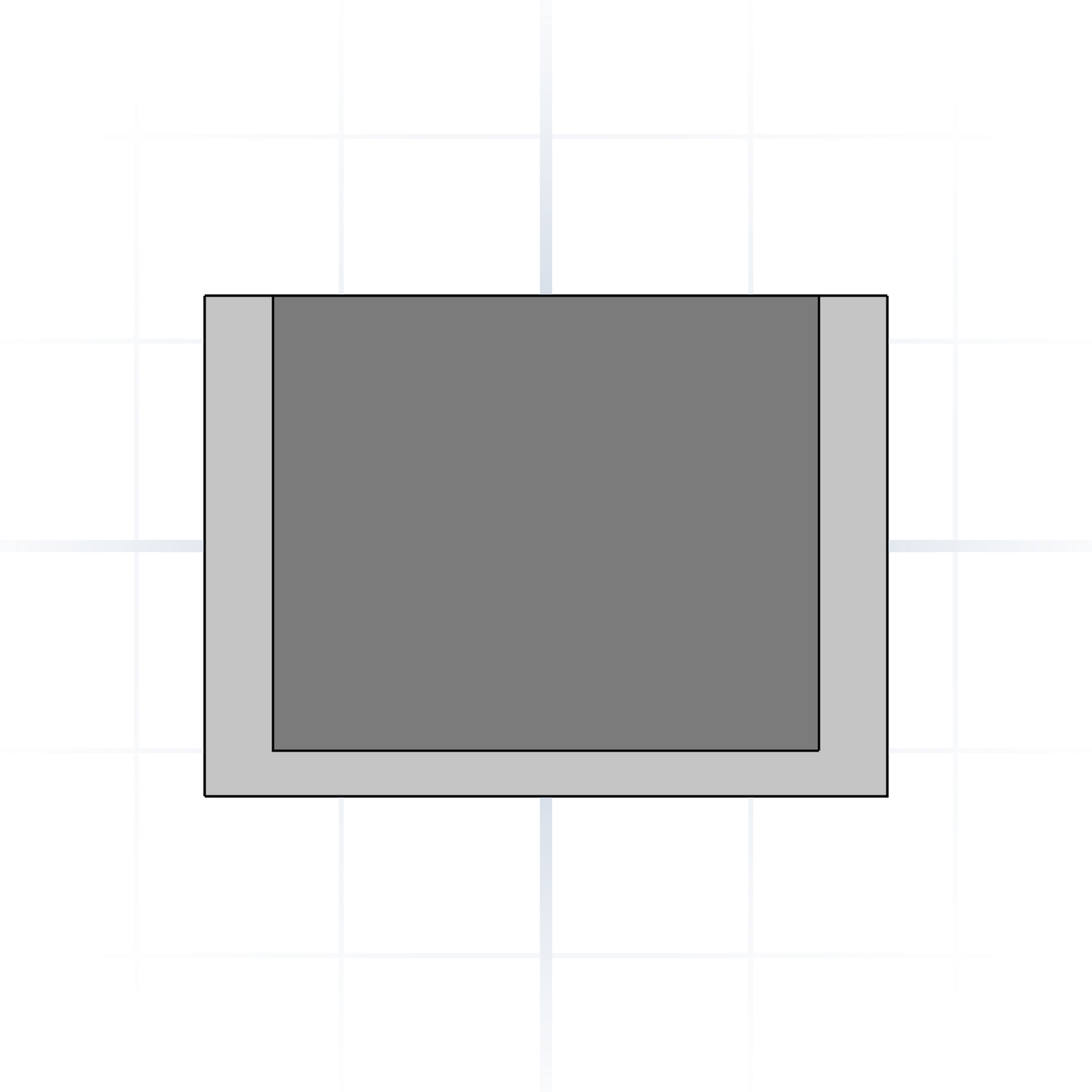
Hollow a solid, leaving walls of a given thickness.
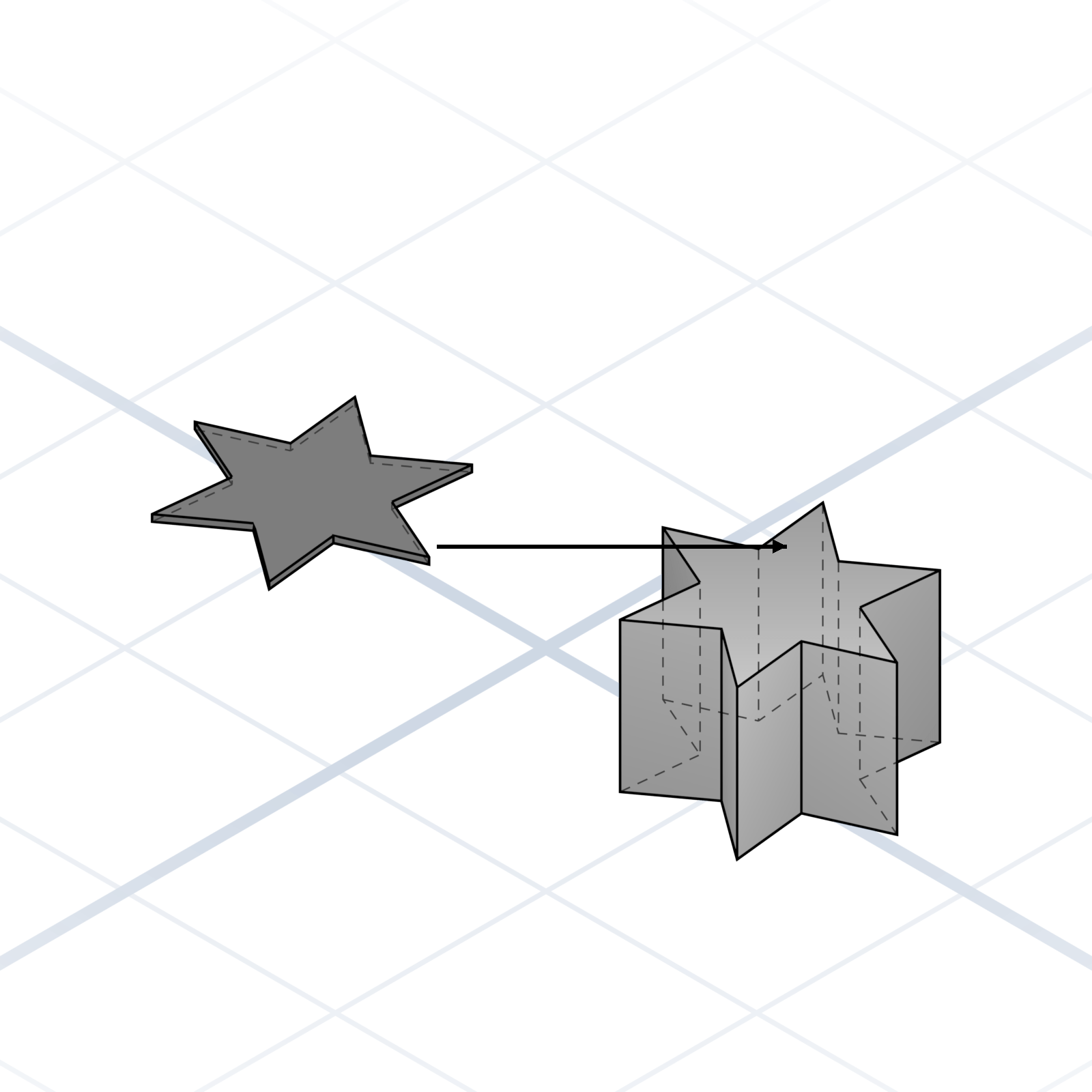
Pull a 2D profile into 3D. The fastest path from sketch to volume.
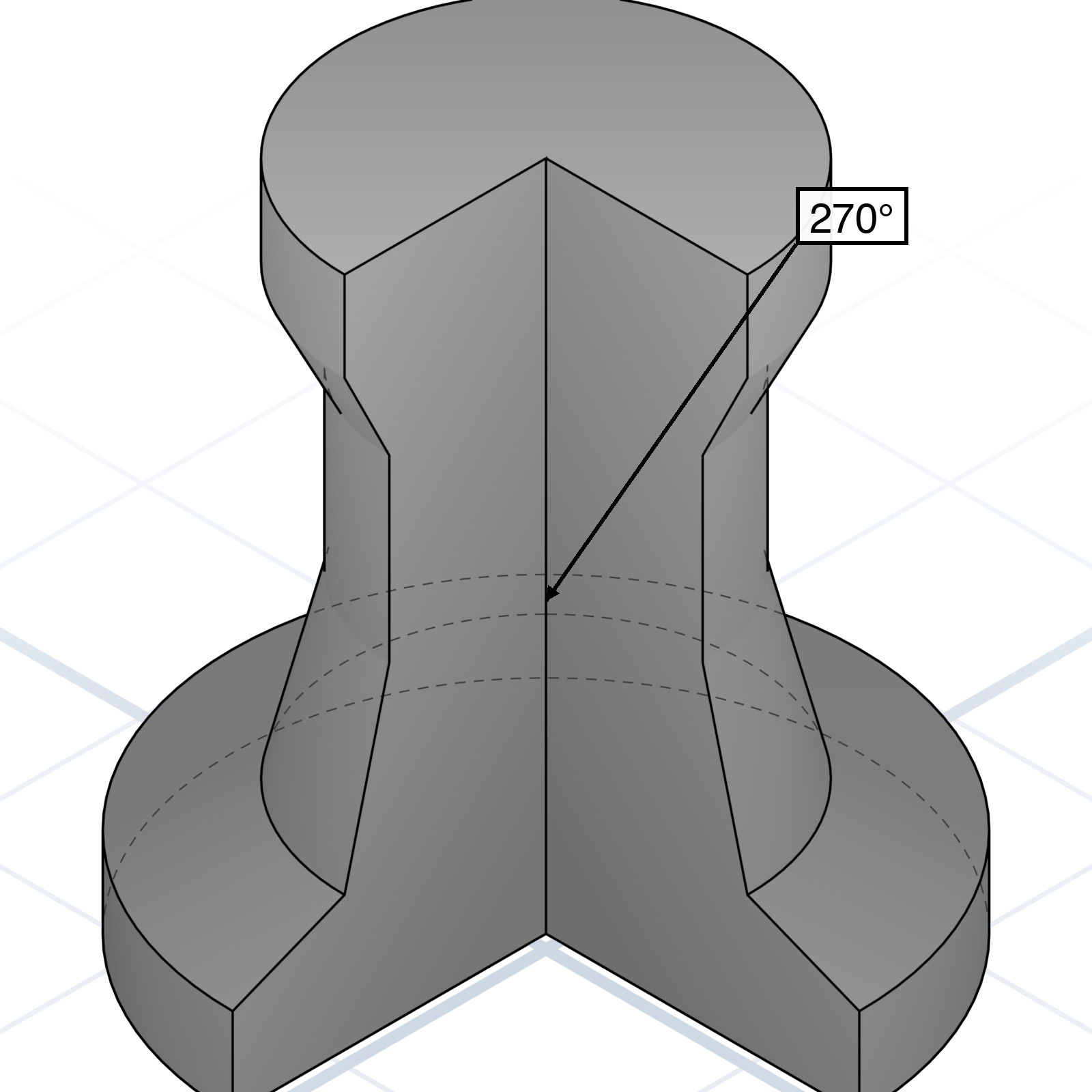
Spin a 2D profile around an axis. Bottles, knobs, and vases come from here.
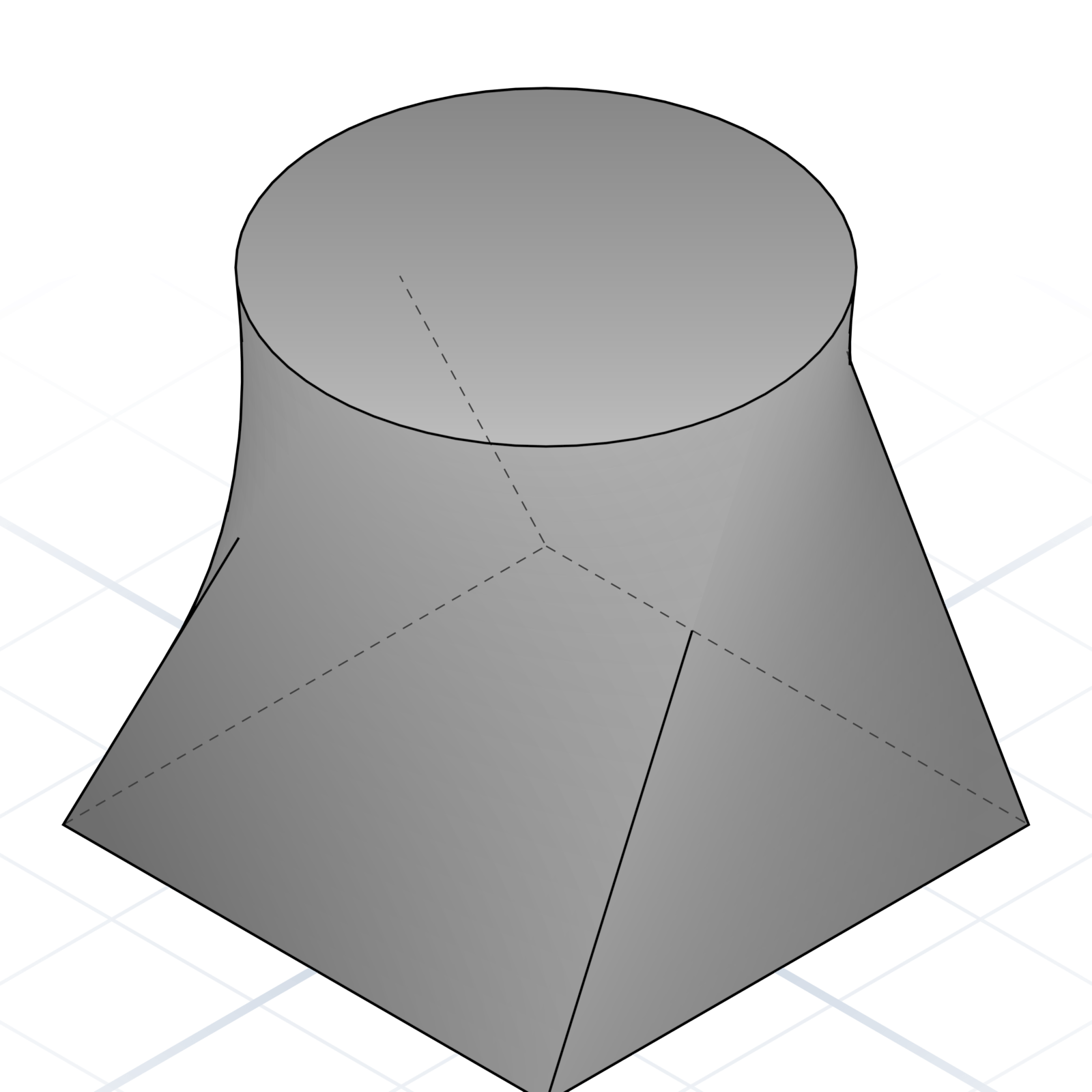
Blend between two or more profiles. Smoothly changes cross-section.
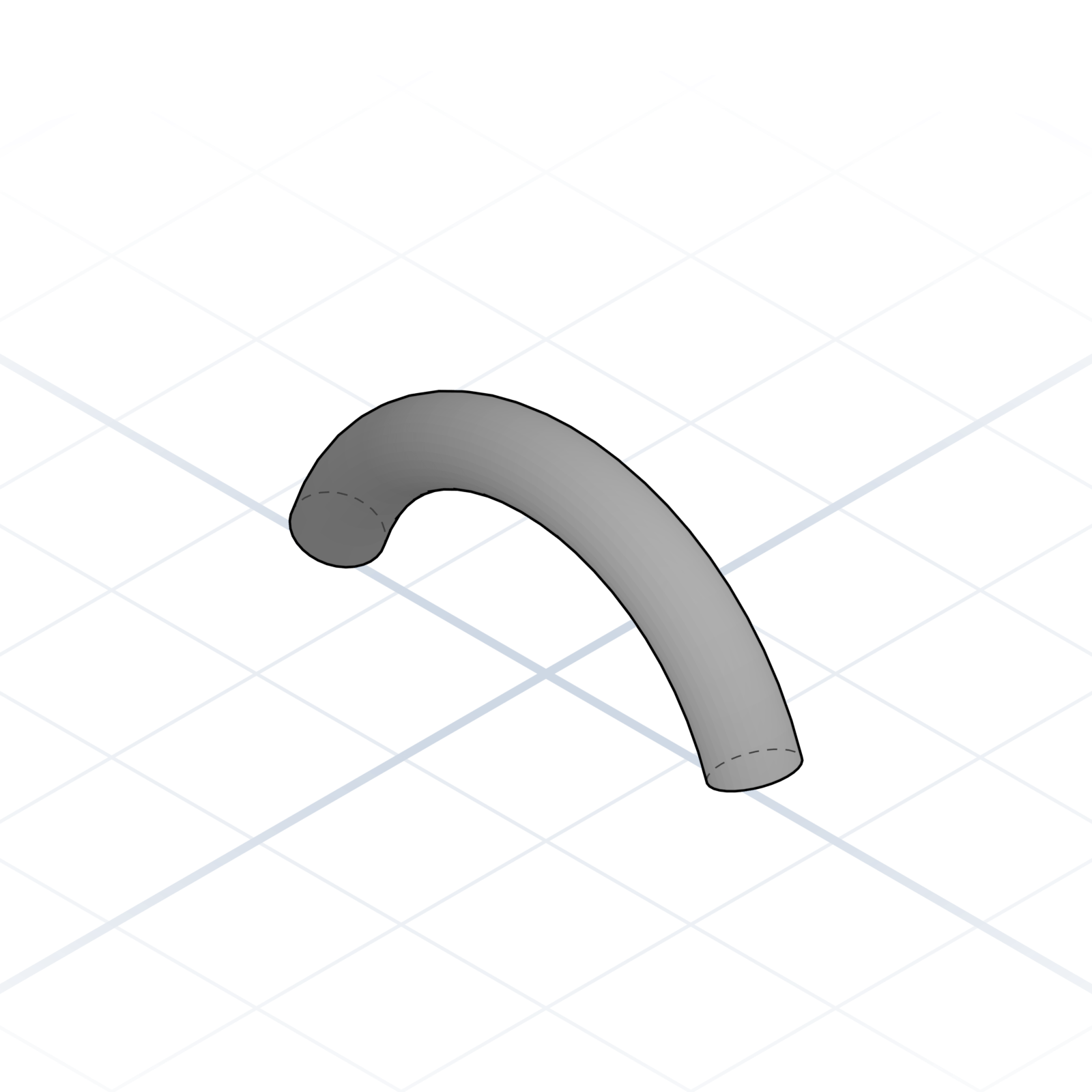
Drag a profile along a path. Pipes, handles, and grooves.
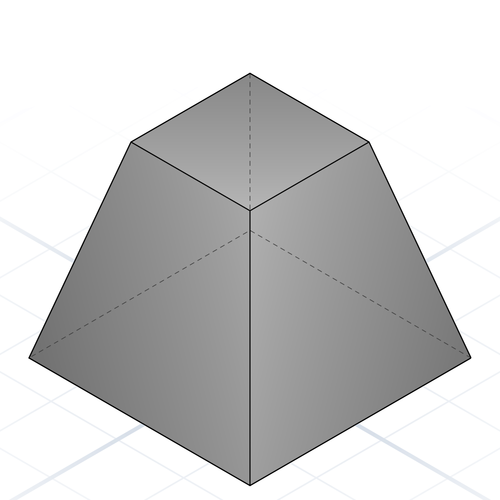
Slant a face by a few degrees. Helps prints release from supports.
How shapes turn into something printable: features, mating geometry, and the hardware your design has to fit around.
Named shapes you add to a part to make it work: mounting, stiffness, sealing, or grip.
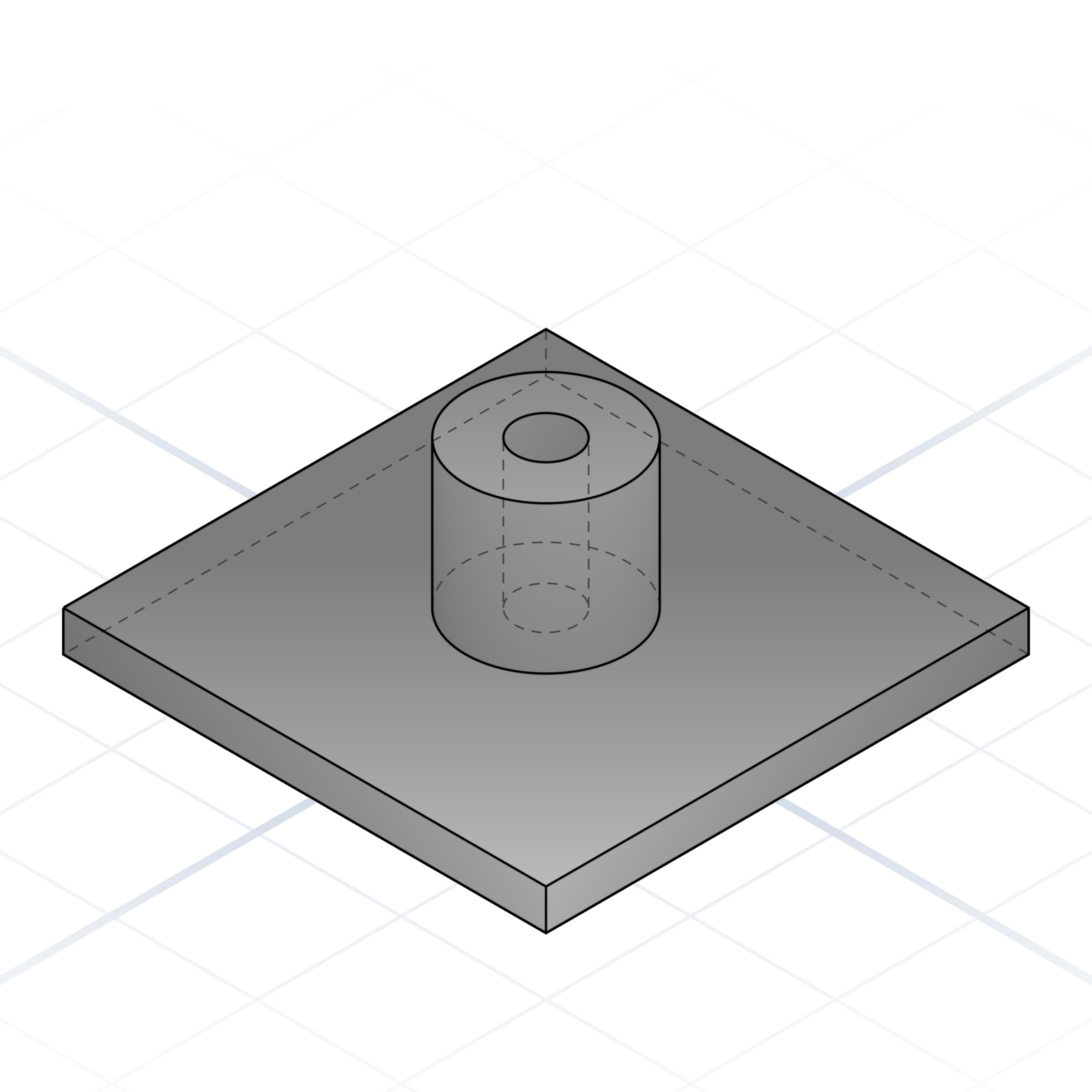
Cylindrical protrusion with a hole, usually for a screw or heat-set insert. The “where parts bolt together” feature.
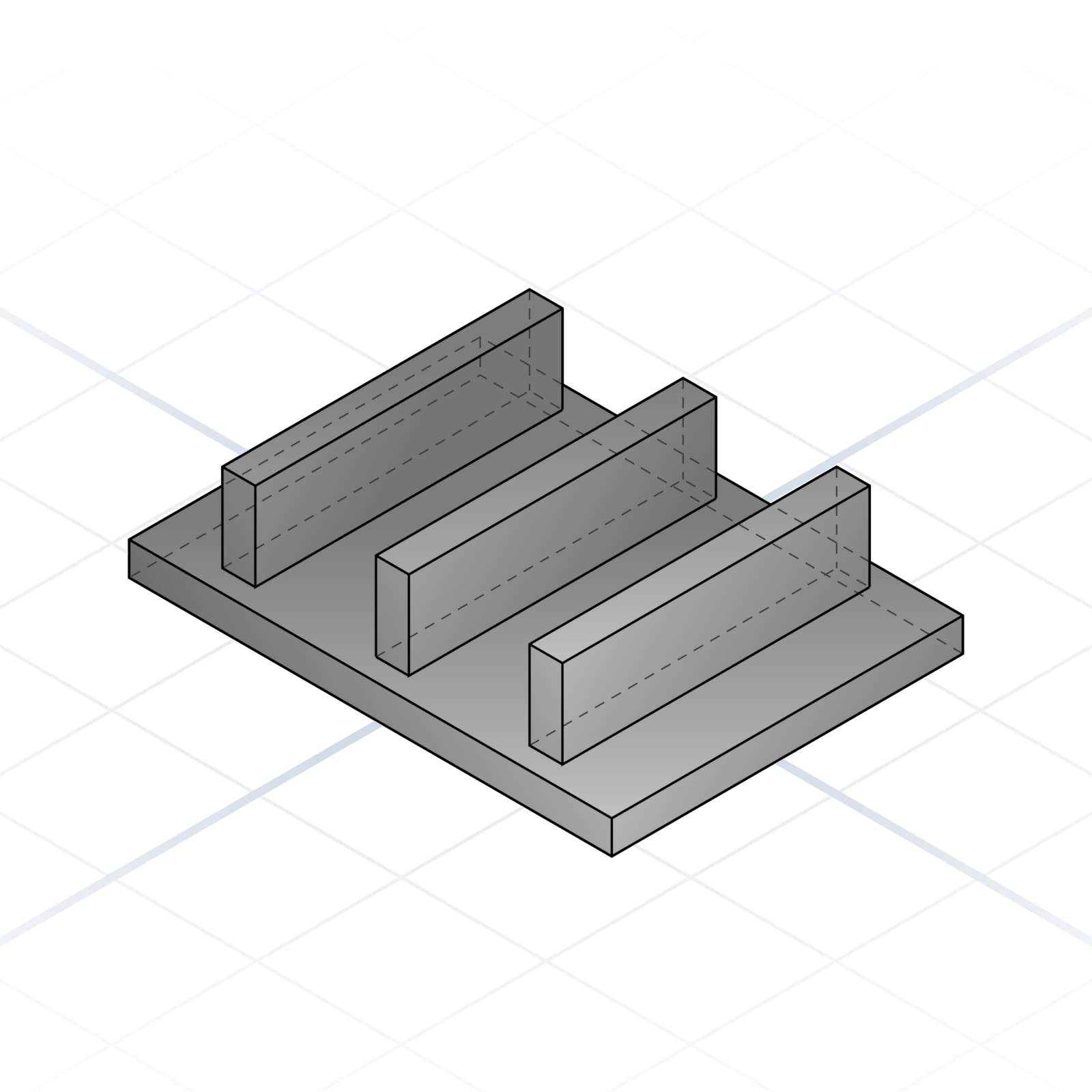
A thin reinforcing fin running along a surface. Stops a flat plate from flexing without doubling the wall thickness.
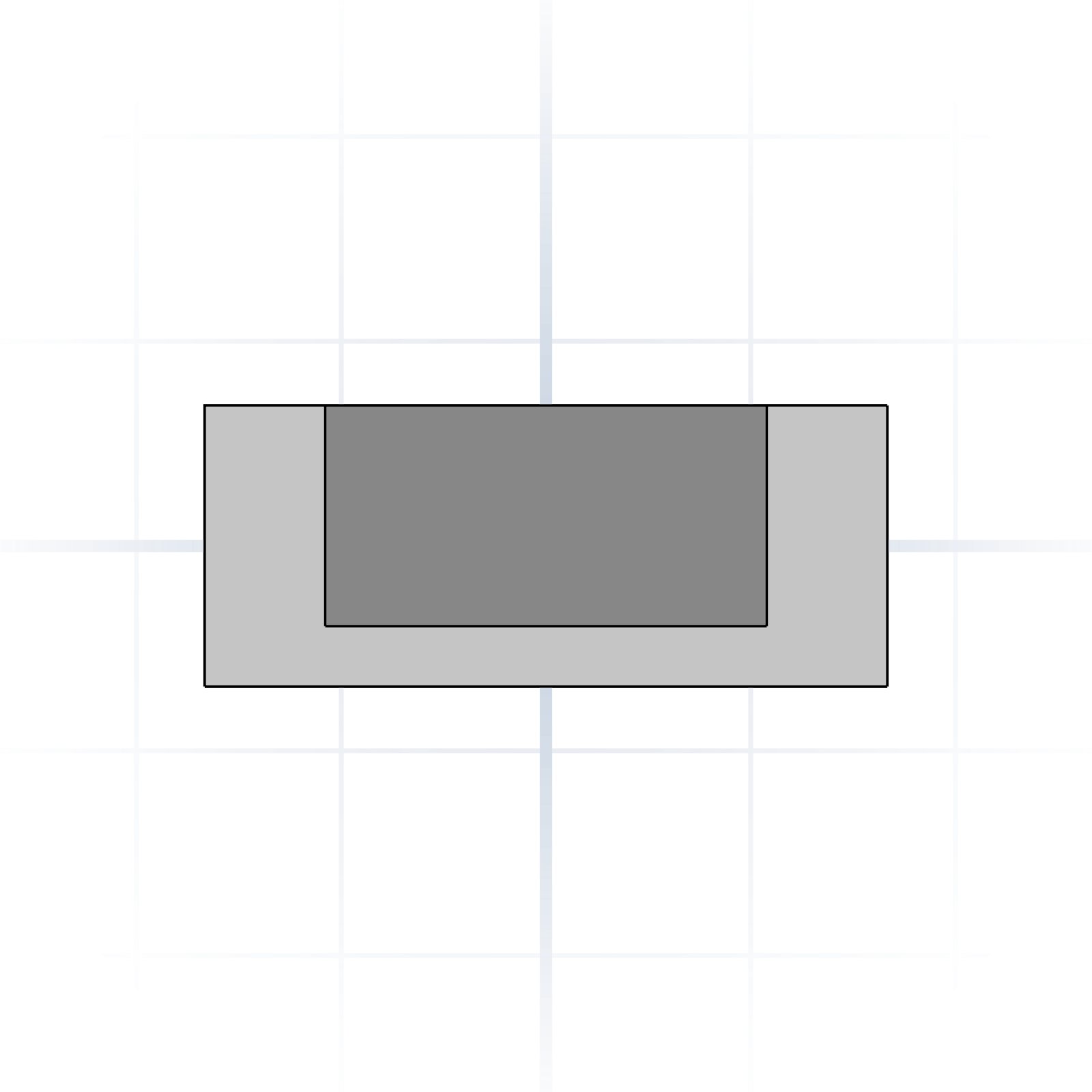
Rectangular cavity in a solid. Cable channels, captive nuts, lightening holes.
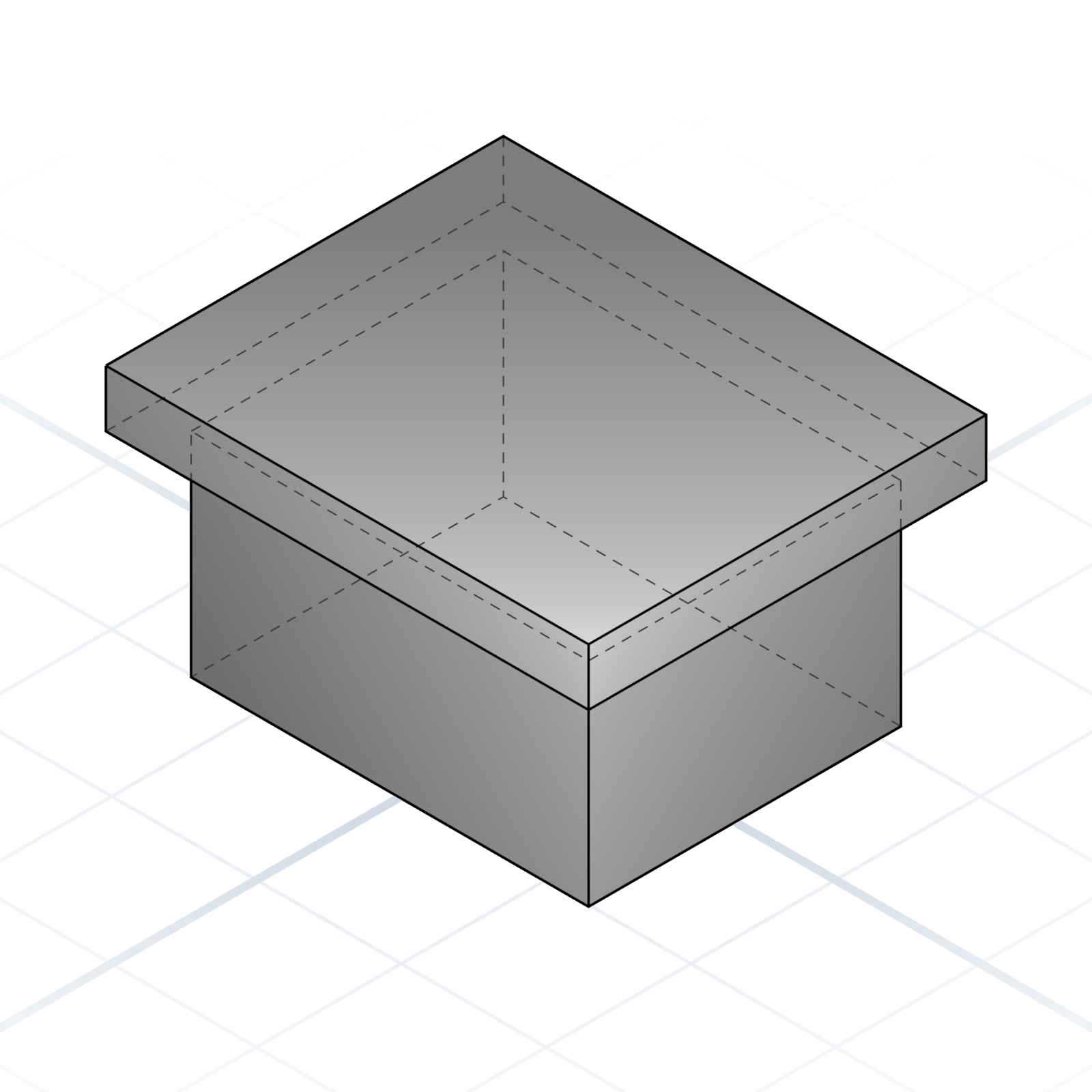
An edge that overhangs the wall below. The rim on a container, the mounting plate on a motor.
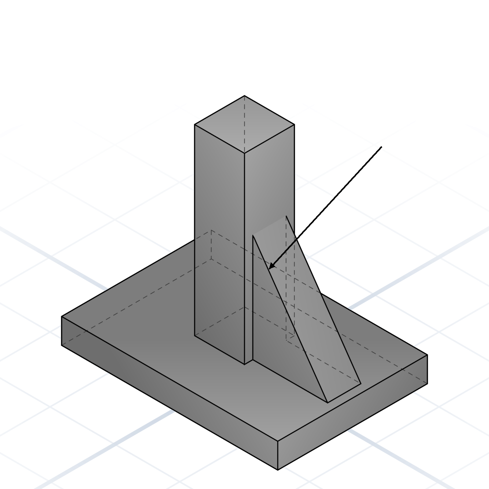
Triangular brace between two perpendicular surfaces. Stiffens a wall without much material.
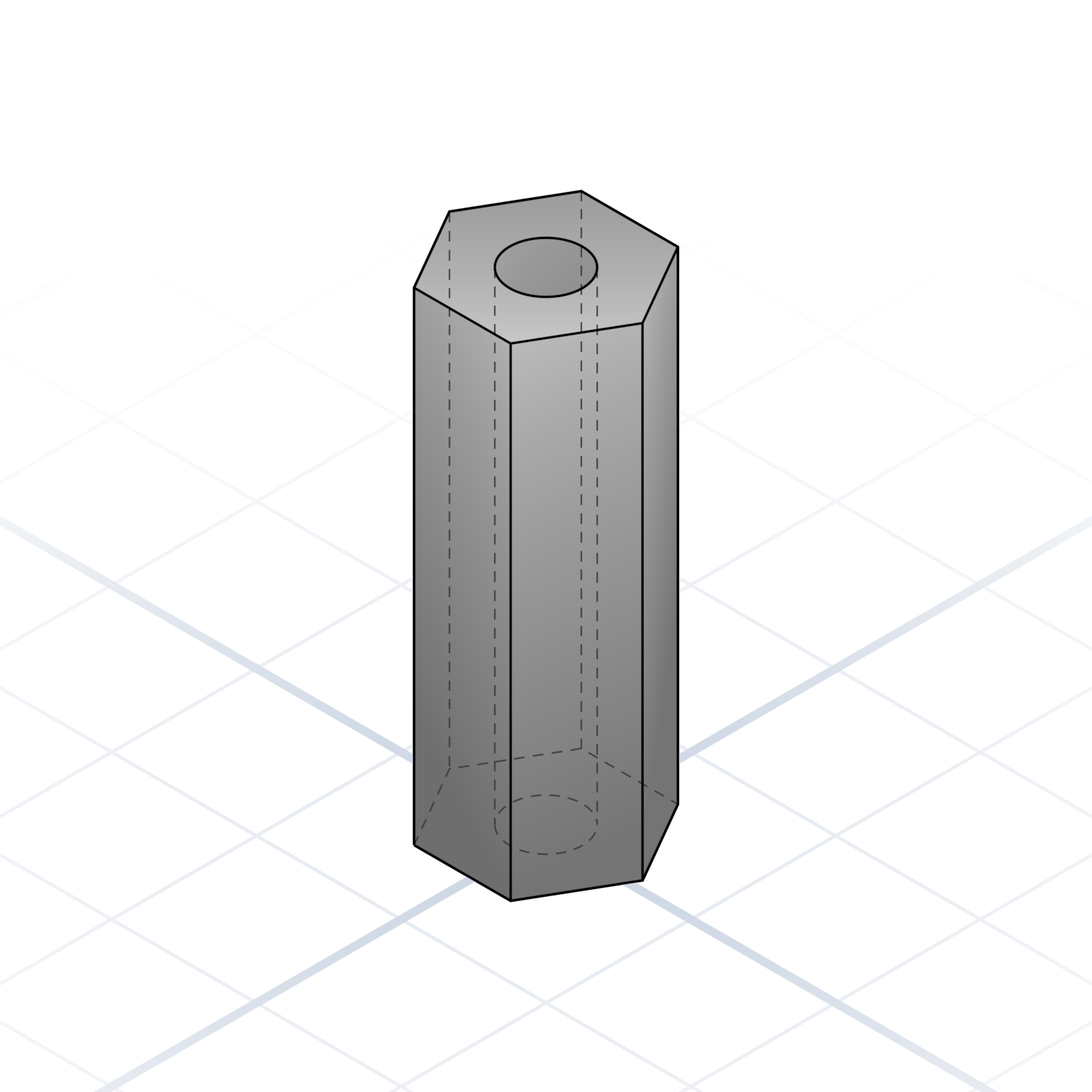
Threaded pillar that holds something at a distance. Hex outside, M3 inside is most common.
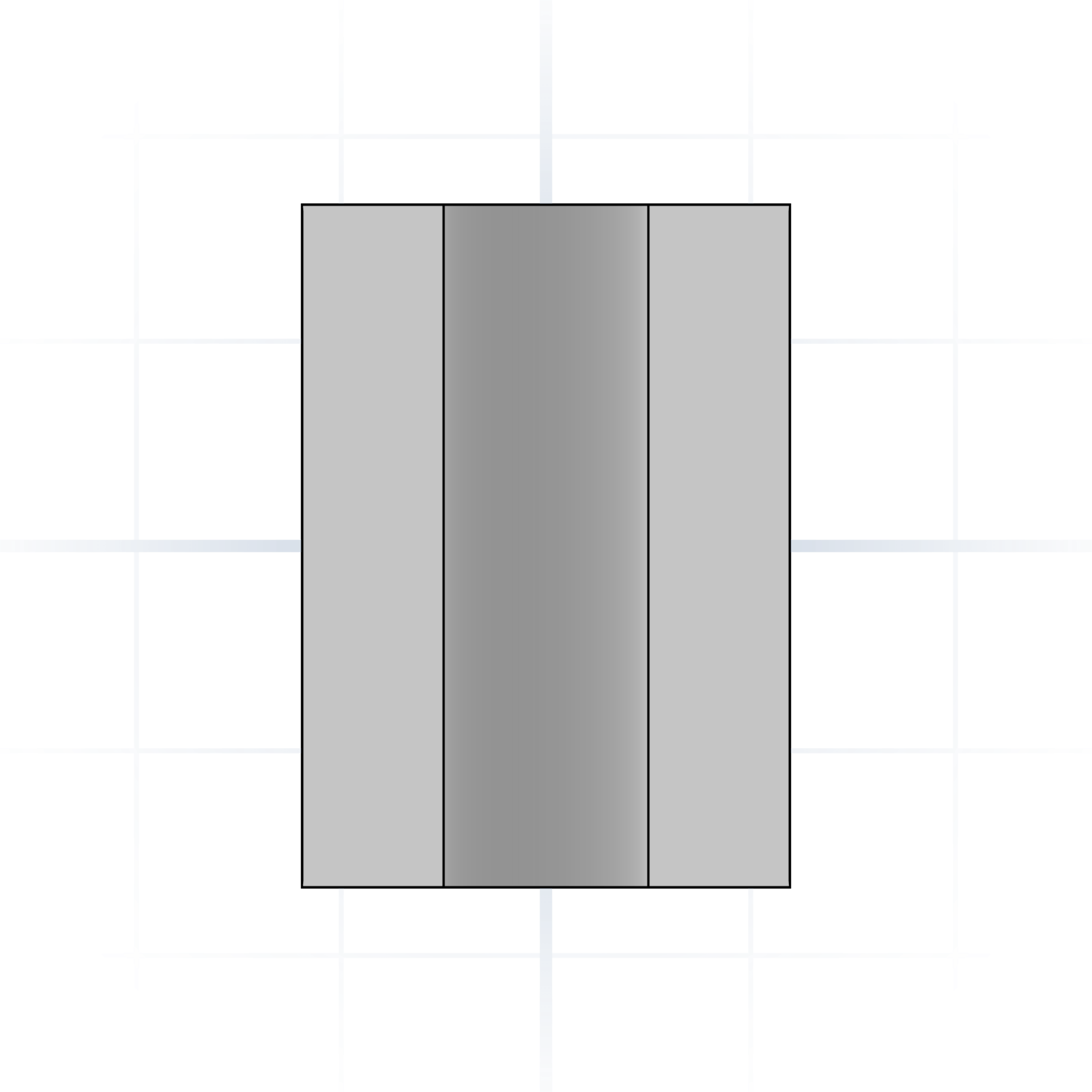
Unthreaded sleeve that holds two parts a fixed distance apart; a screw passes straight through. Use it when you need an even gap between two parts.
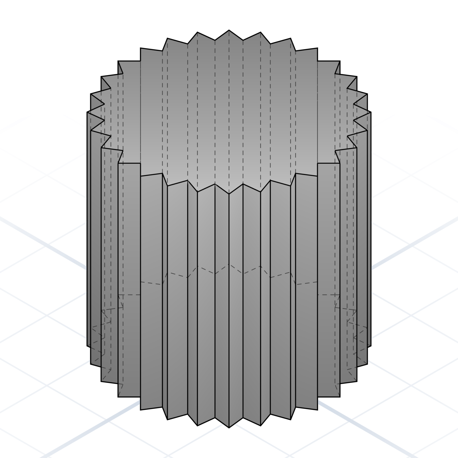
Textured grip pattern on a cylindrical surface. Thumb screws and adjustment knobs use it so fingers don’t slip.
Five ways to put a name, number, or icon on a printed part. Which one you pick comes down to two things: how deep the letters go and whether you need a second colour.
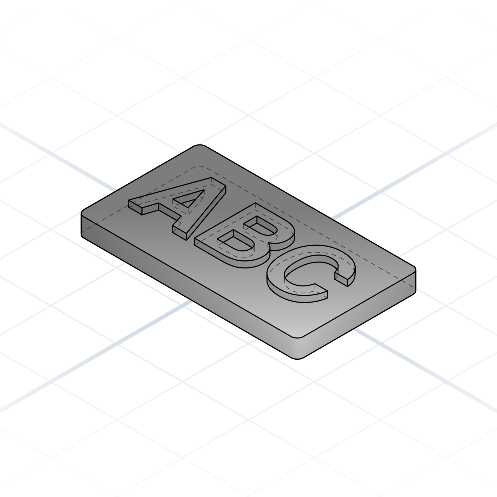
Letters rise ~1 mm above the surface. Cleanest to print and easiest to read. The default when one colour is fine.
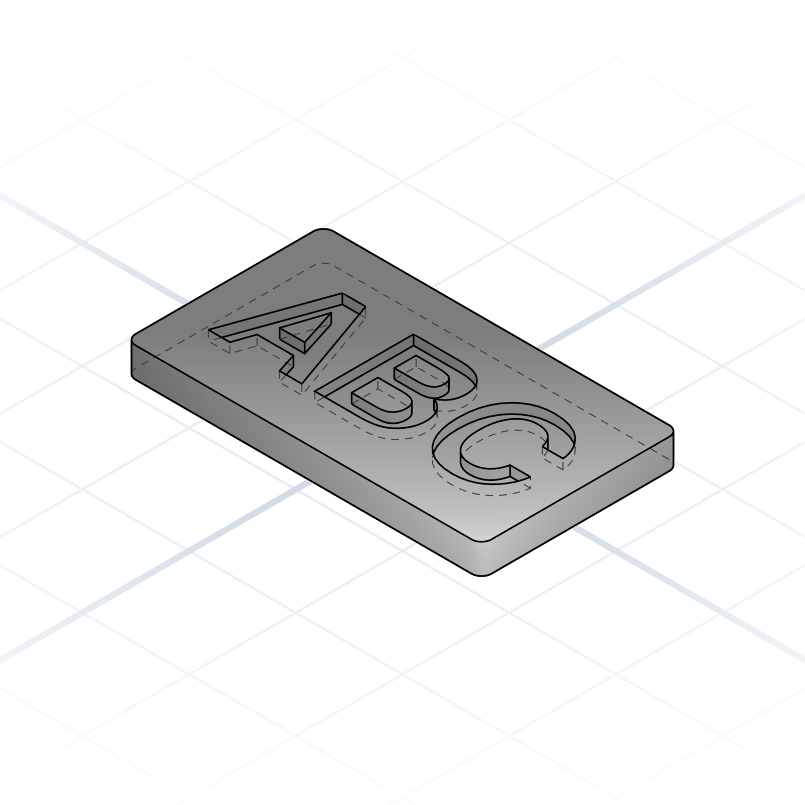
Letters cut ~1 mm into the surface. Robust against wear and scuffing, the go-to for serial numbers and stamped marks.
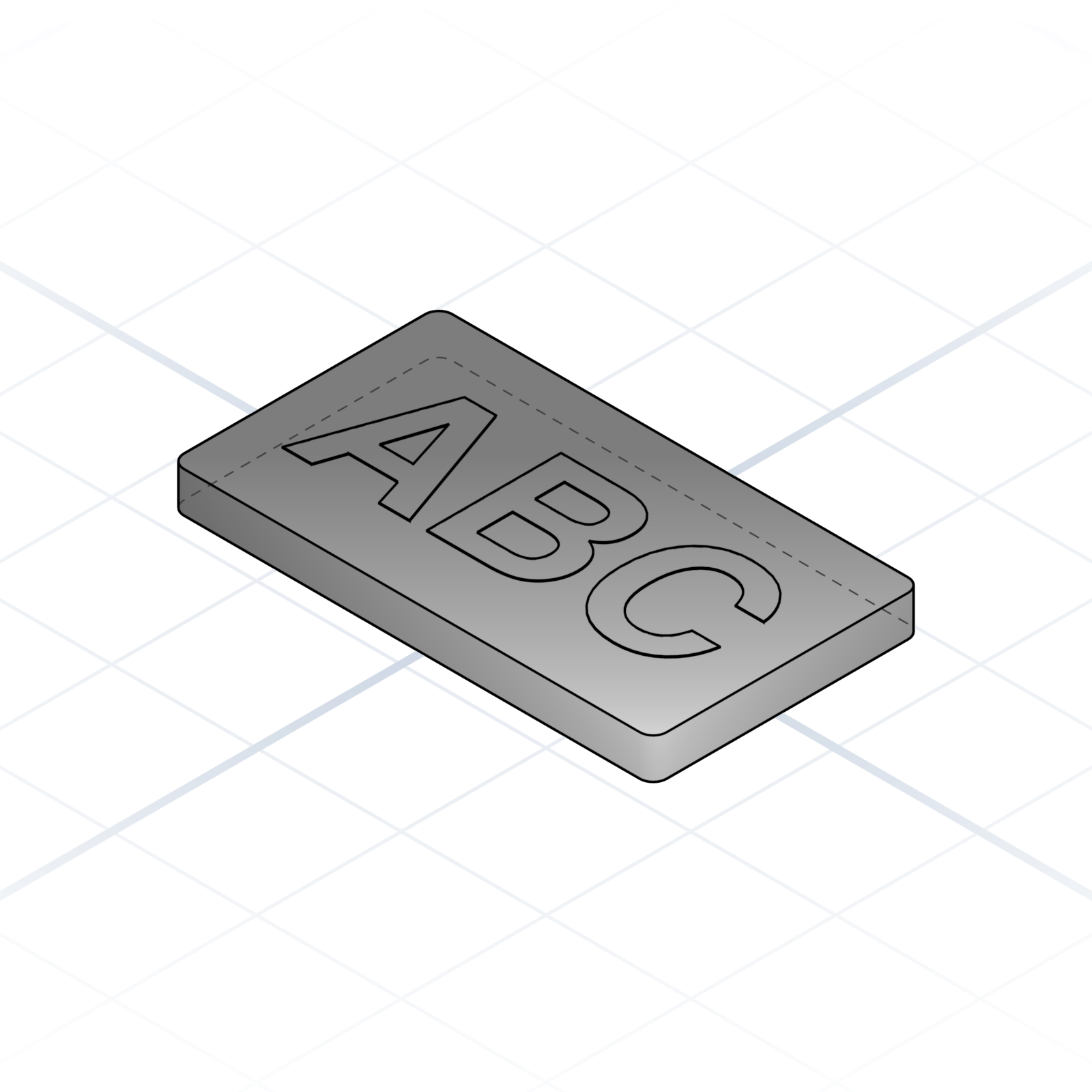
Pocket refilled with a second filament at the exact same height. Needs a printer that changes colours automatically, or you swap the filament by hand. Reads like a printed sticker.
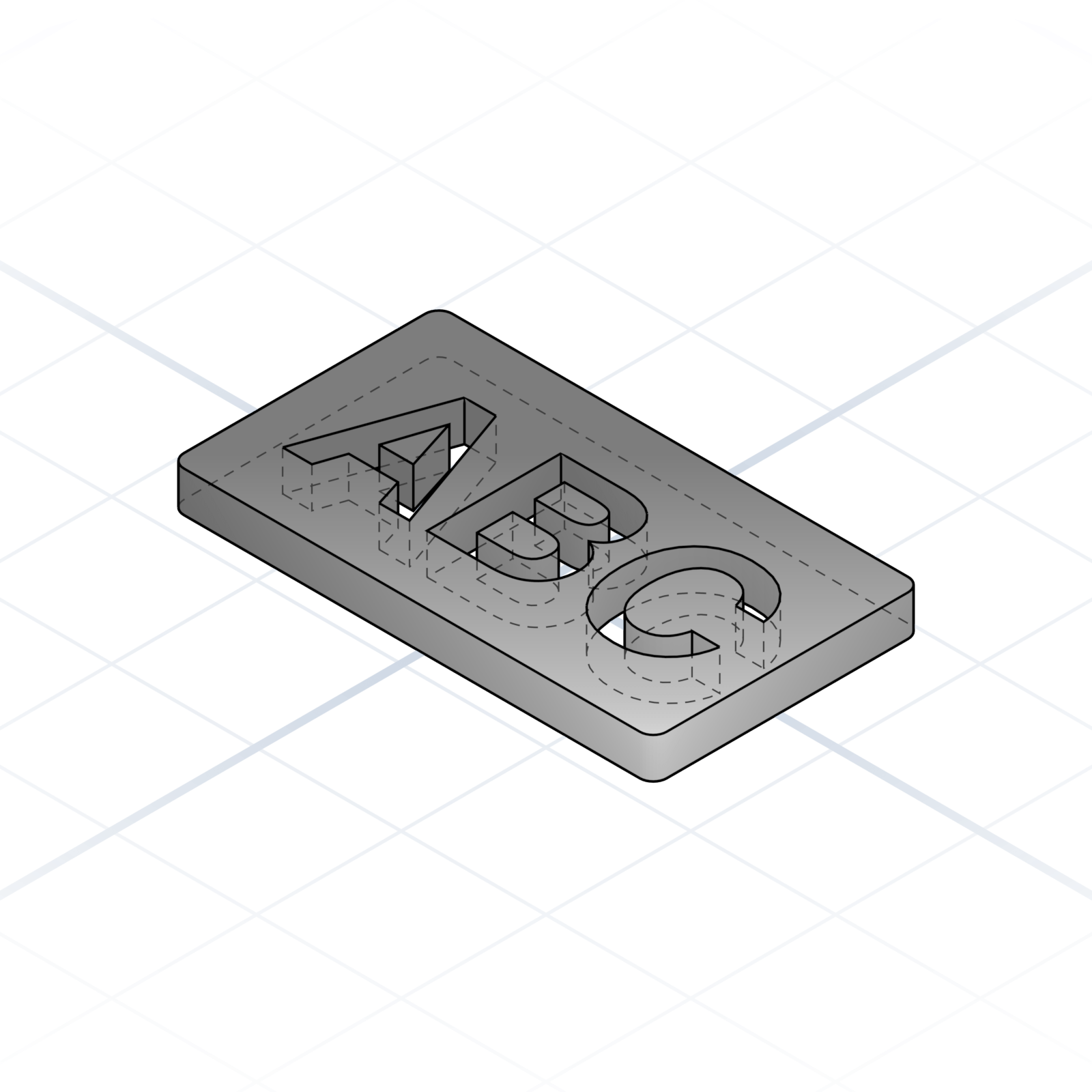
Letters cut all the way through the plate. Perfect for signage that lets light through. The centres of letters like “O” or “A” need a bridge or they fall out.
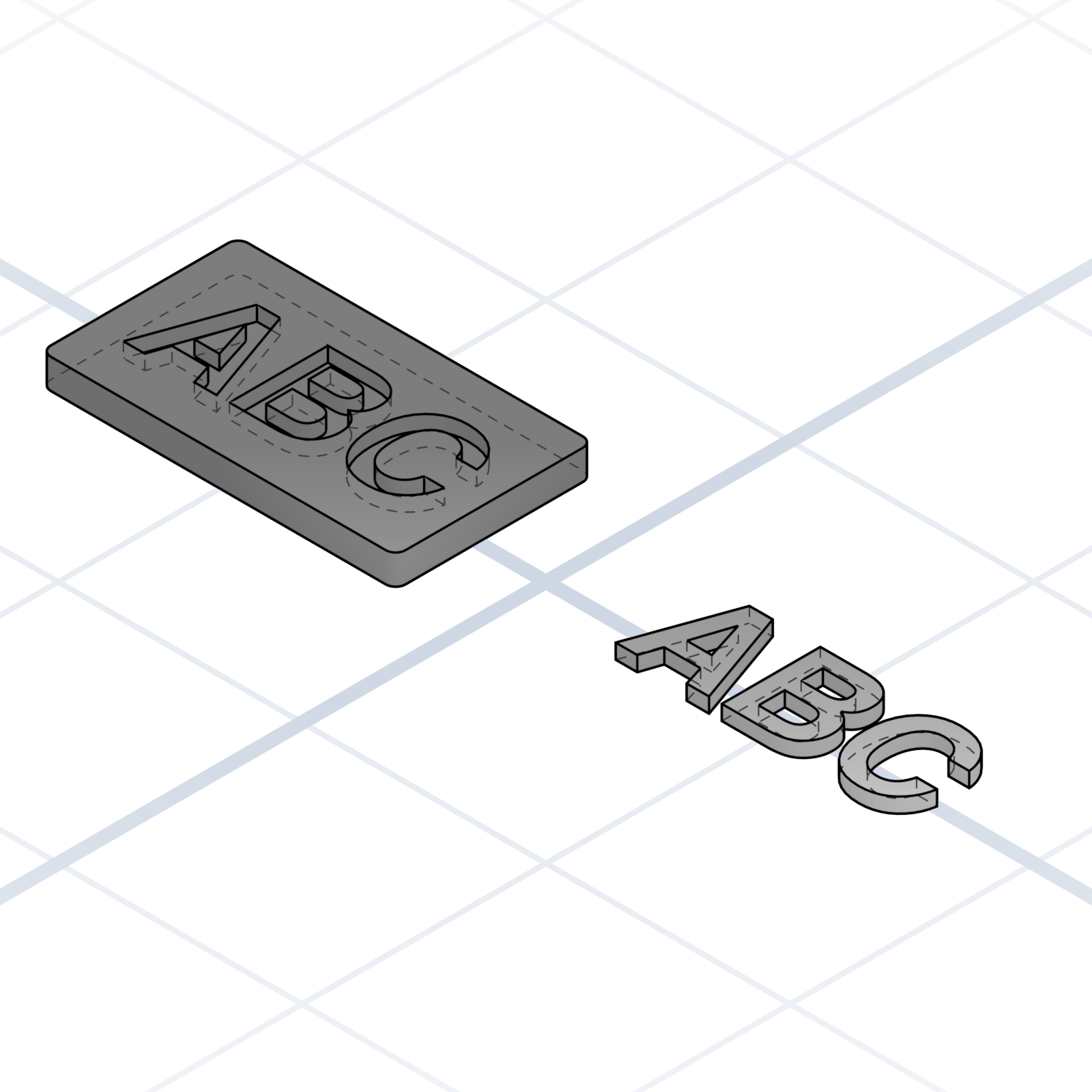
Print a plate with a text-shaped pocket and the letters as a separate piece in a contrasting colour, then glue them in. Single-extruder friendly.
Not all holes are equal. The right name avoids a redesign cycle later.
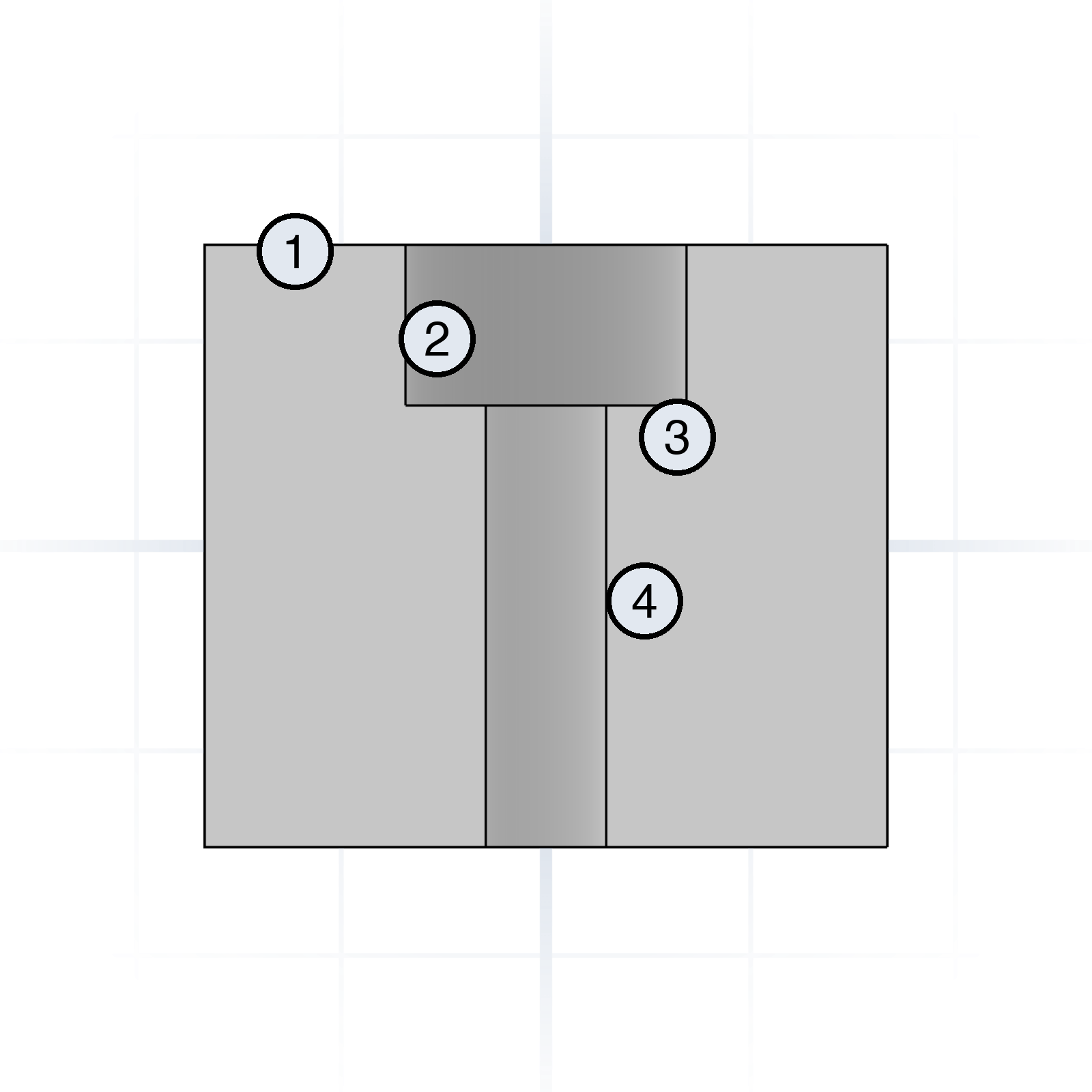
Naming the layers makes the prompt unambiguous: “M3 clearance, 6 mm counterbore, 3 mm deep”.
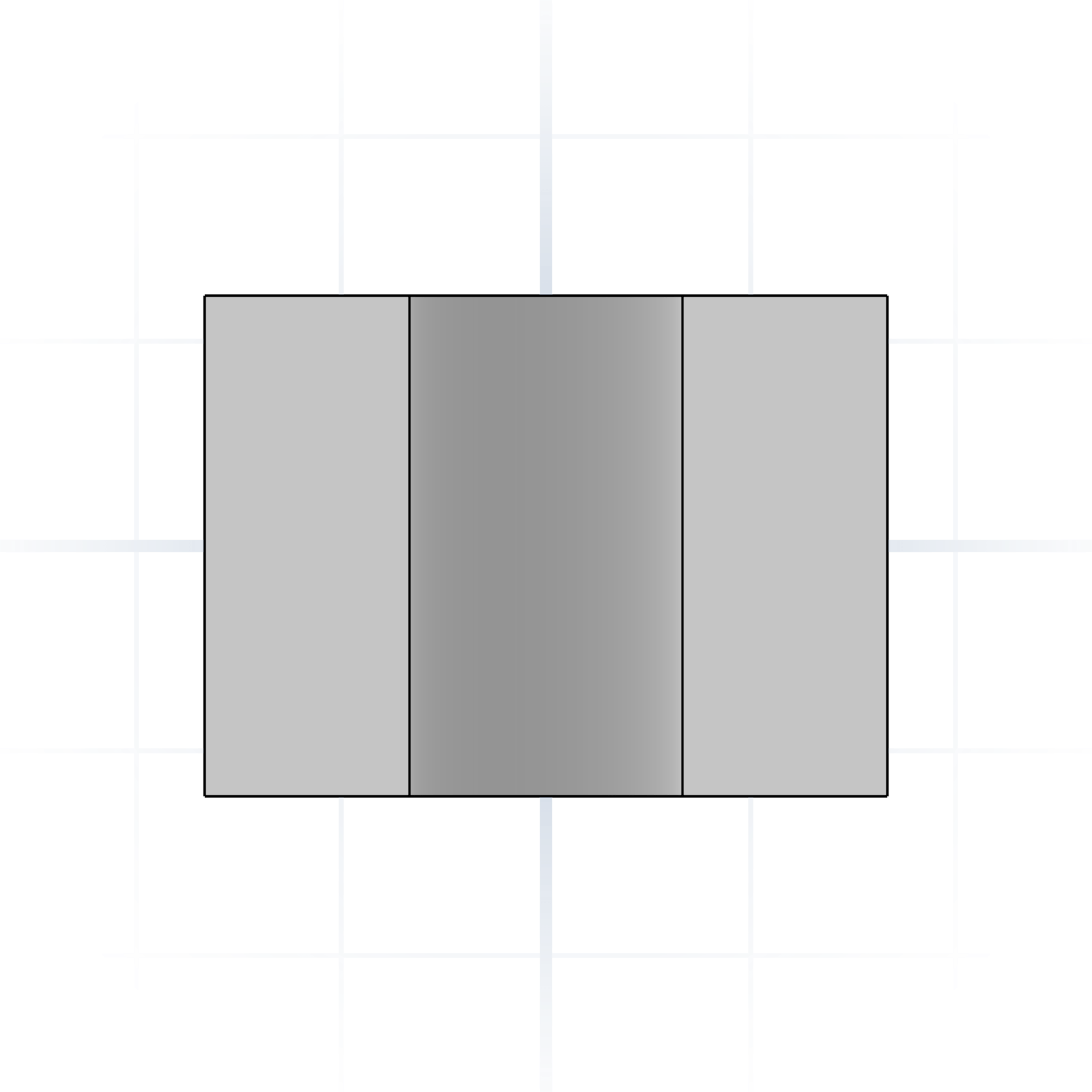
Goes all the way through the part.
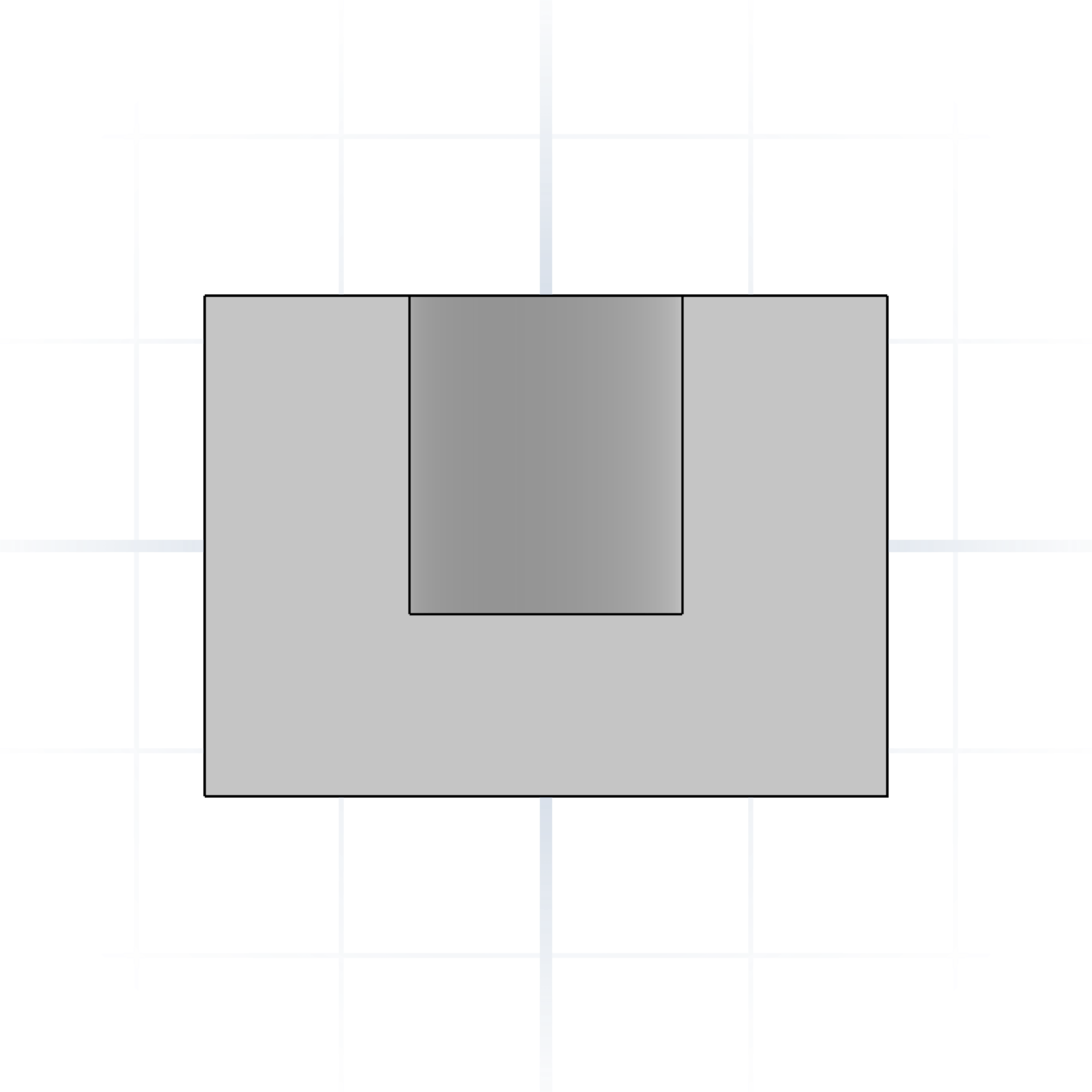
Stops at a depth. Say “blind, 8 mm deep”.
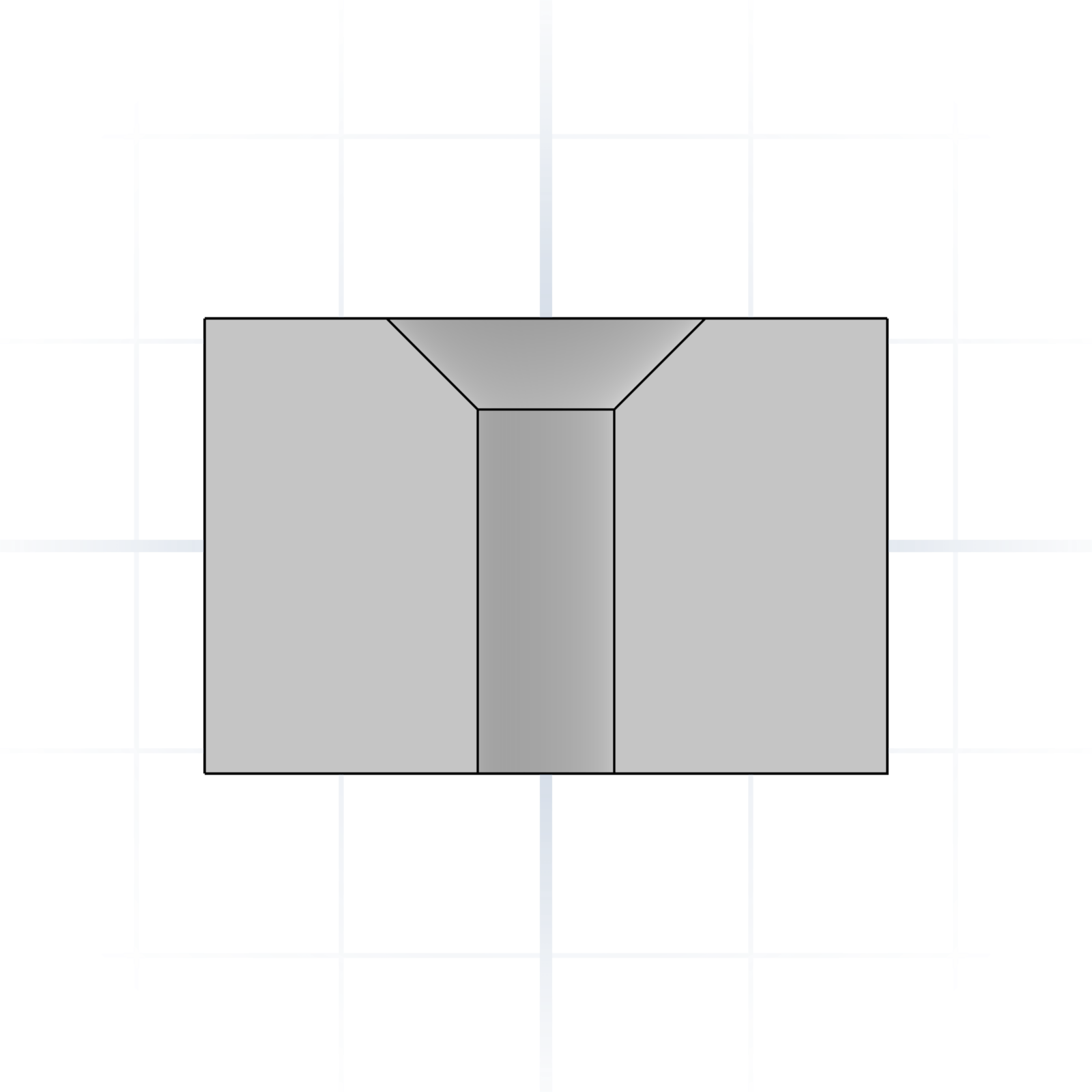
Cone-shaped recess so a flat-head screw sits flush. The chamfer angle matches the screw head (usually 90°).
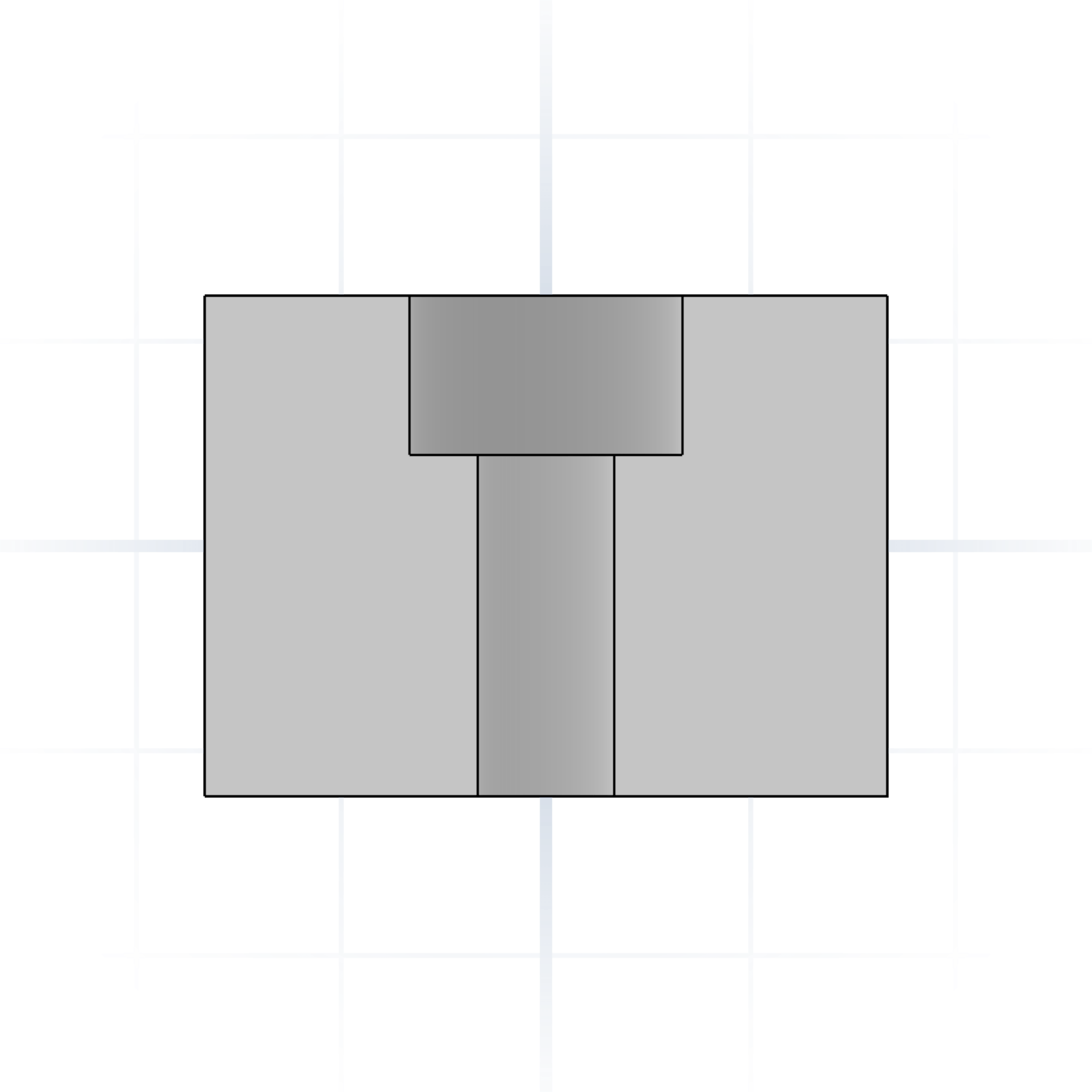
Cylindrical recess so a socket-head cap drops below the surface. Call out the diameter and depth.
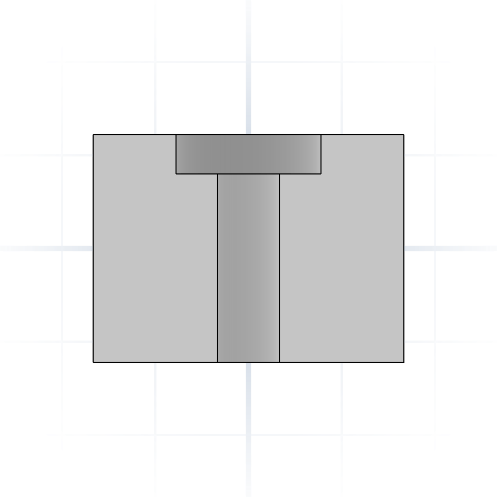
Shallow counterbore that flattens a rough surface for a washer or bolt head to seat.
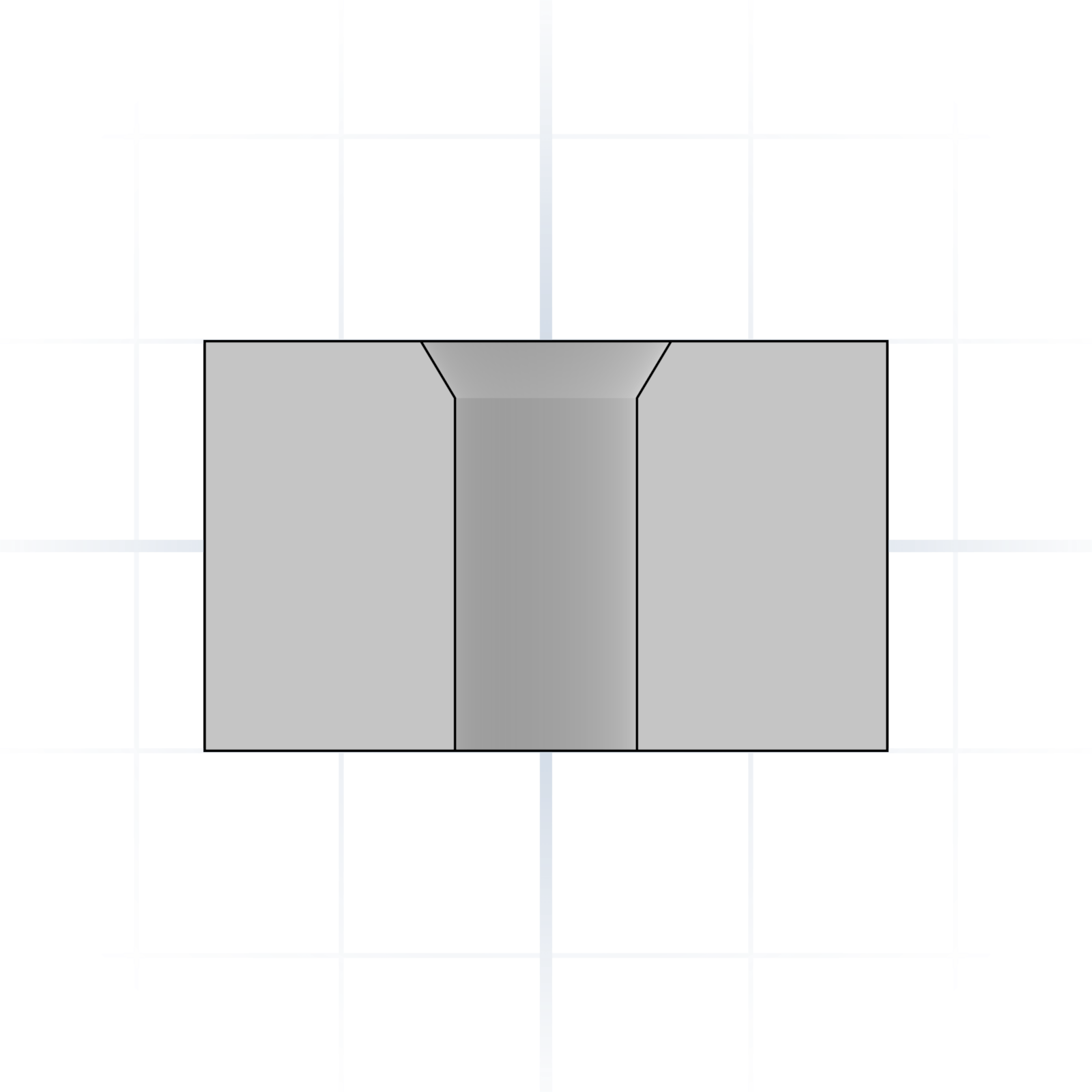
Sized so a screw passes freely without engaging threads. Typically 0.2–0.5 mm wider than nominal.
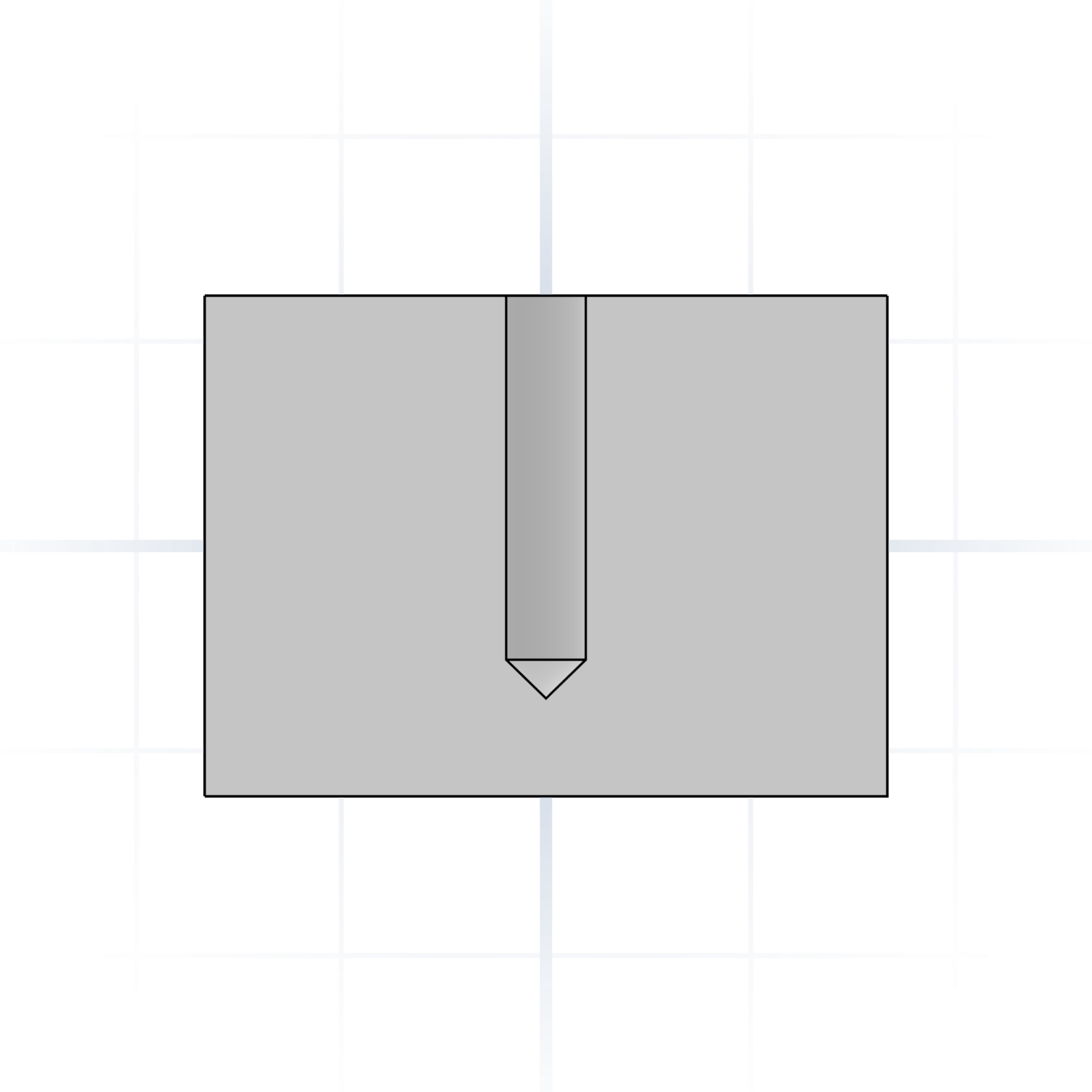
Undersized hole for a self-tapping screw to cut threads into. Slightly smaller than the screw’s nominal diameter.
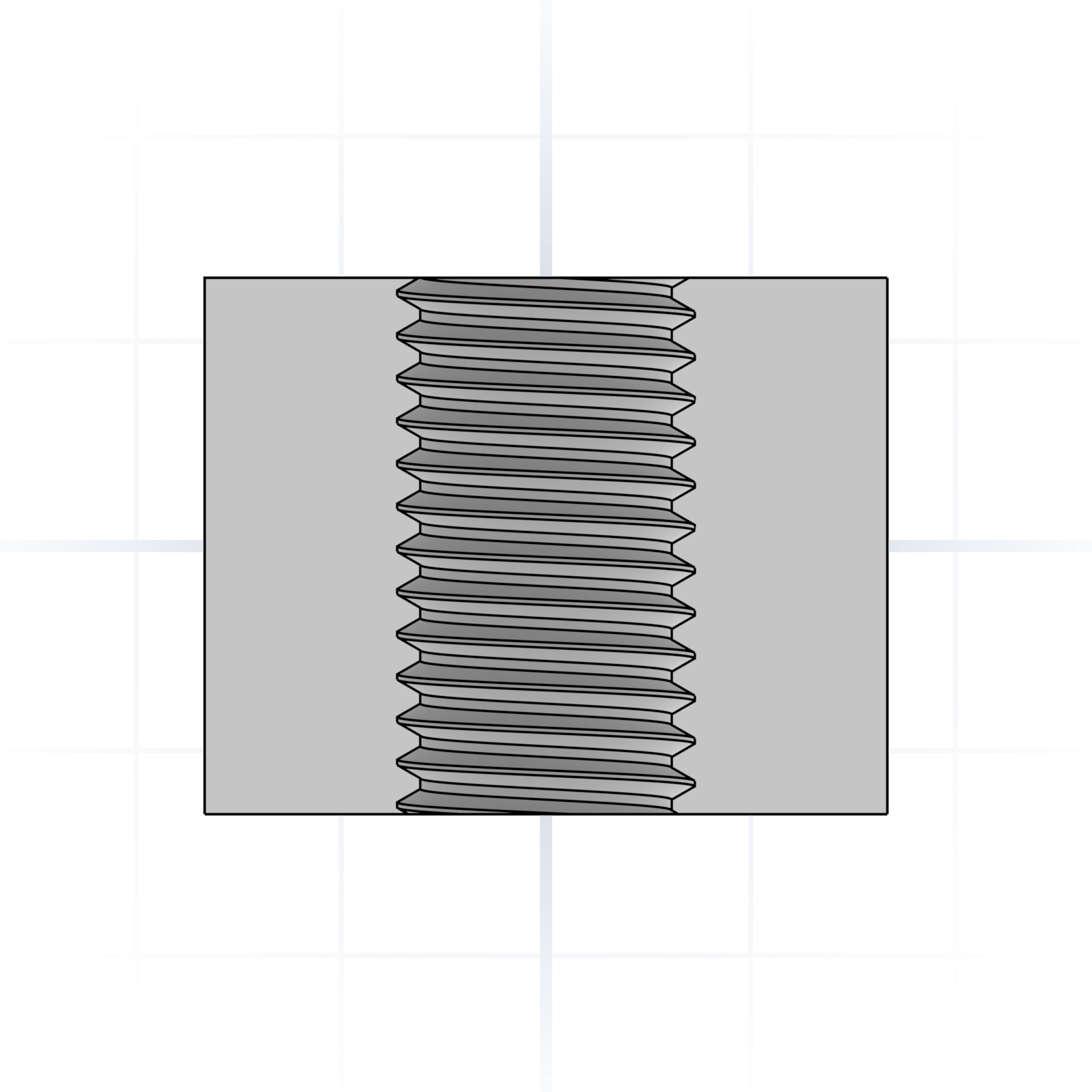
Has internal threads. Call out the size (e.g. M6). Which sizes are worth printing is on the Fasteners page.
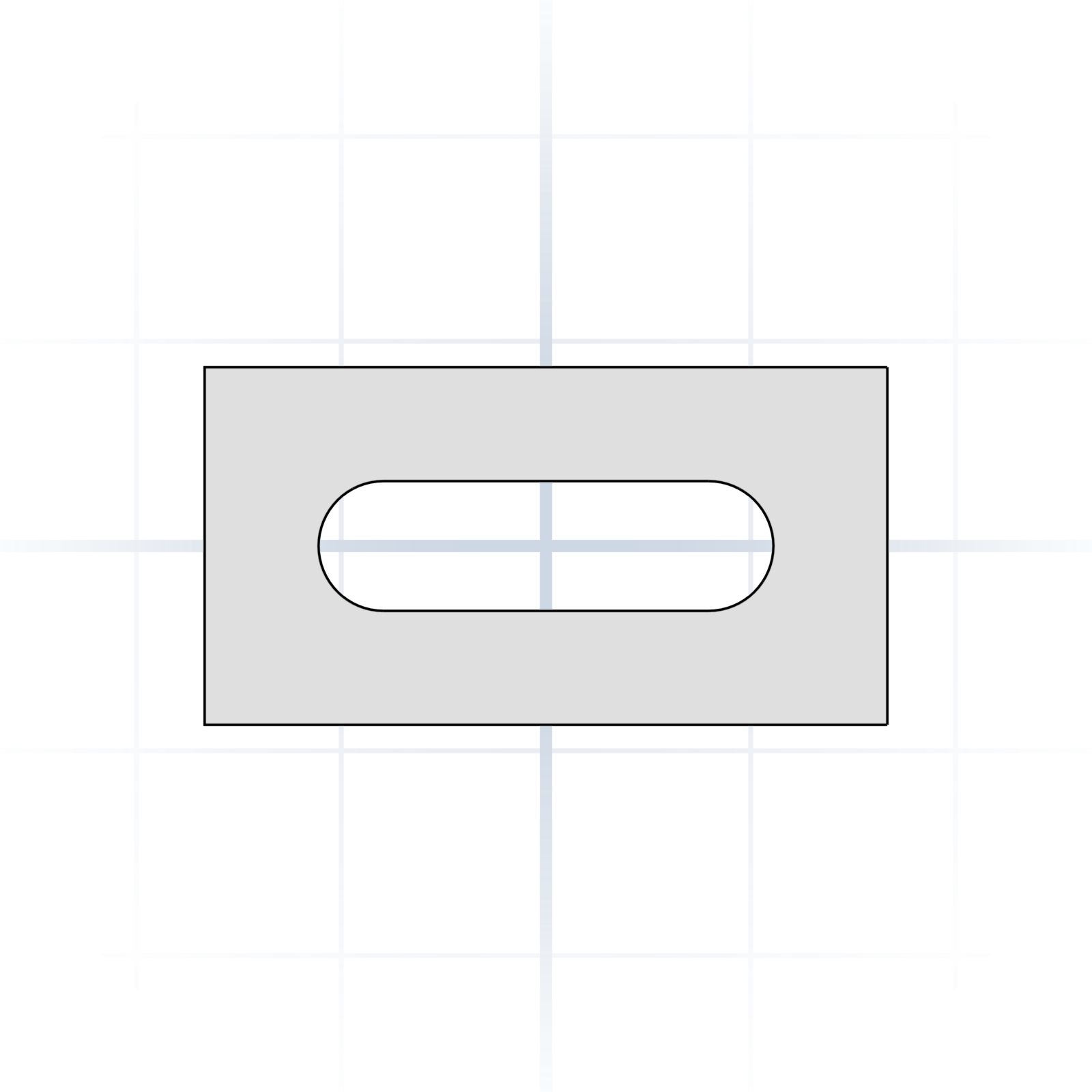
An elongated hole with rounded ends. Length and width, not just diameter.
How tight or loose two parts go together. Values are clearance on diameter for an average filament printer; halve them if you apply the gap to each side.
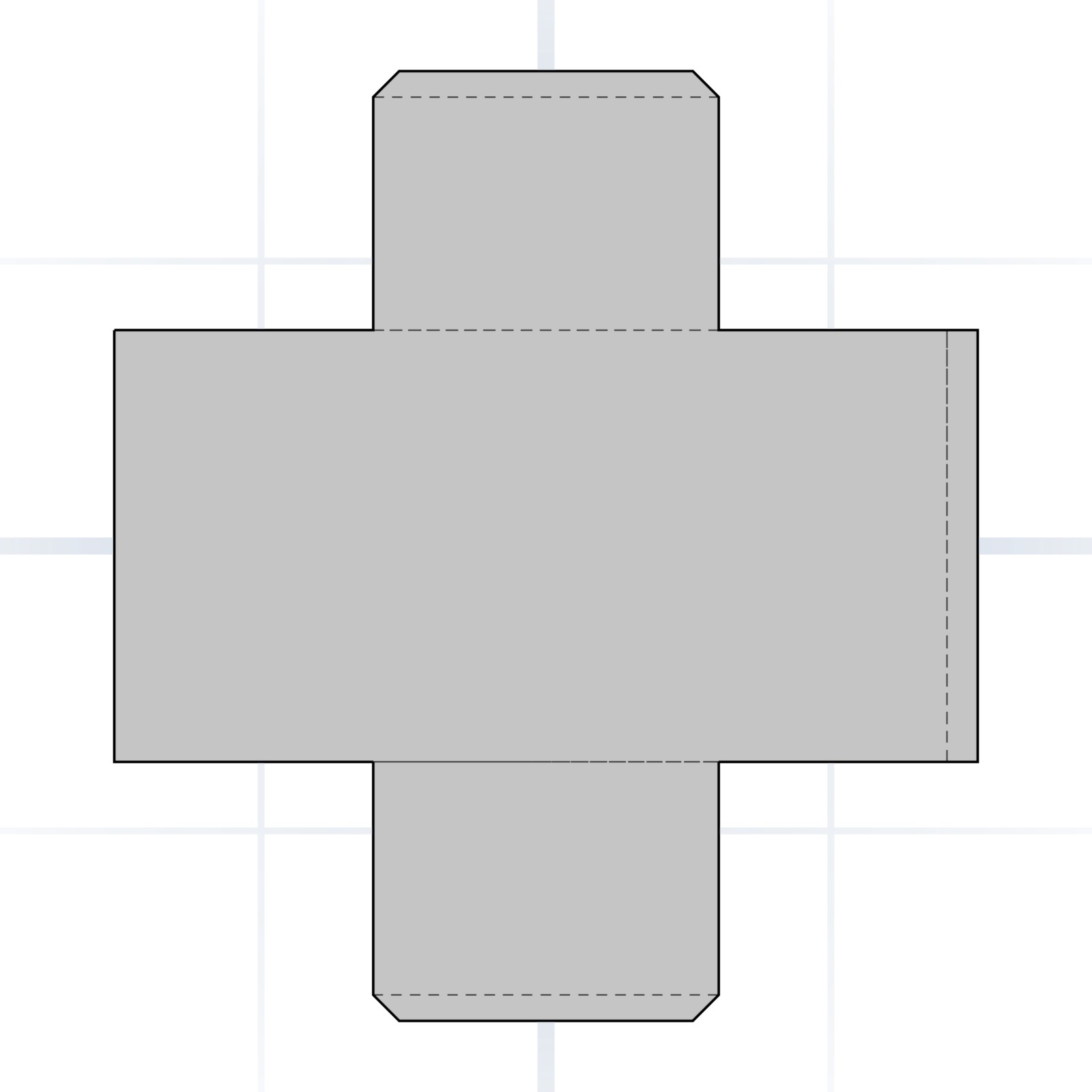
Needs a press or a mallet. Permanent: bearings, dowel pins. Pure interference is unreliable on FDM, so add crush ribs and a chamfered lead-in. FDM: −0.1 to +0.1 mm on diameter.
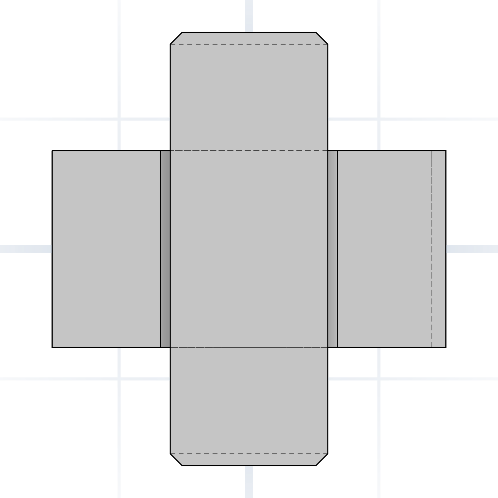
Assembles with light hand pressure (snug, but removable). Battery doors, sensor mounts, removable caps. FDM: +0.1 to +0.2 mm on diameter.
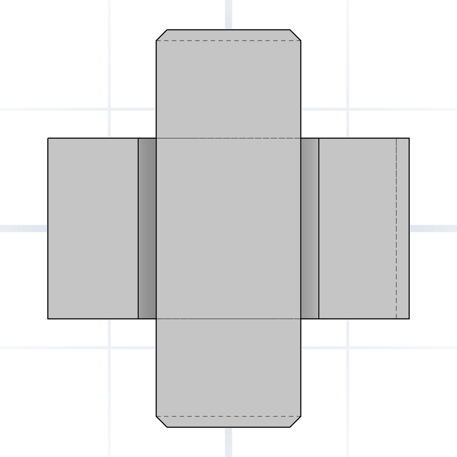
Slides without wobble. Drawer rails, pistons, sliding lids. FDM: +0.3 to +0.5 mm on diameter (≈ 0.15–0.25 mm per side).
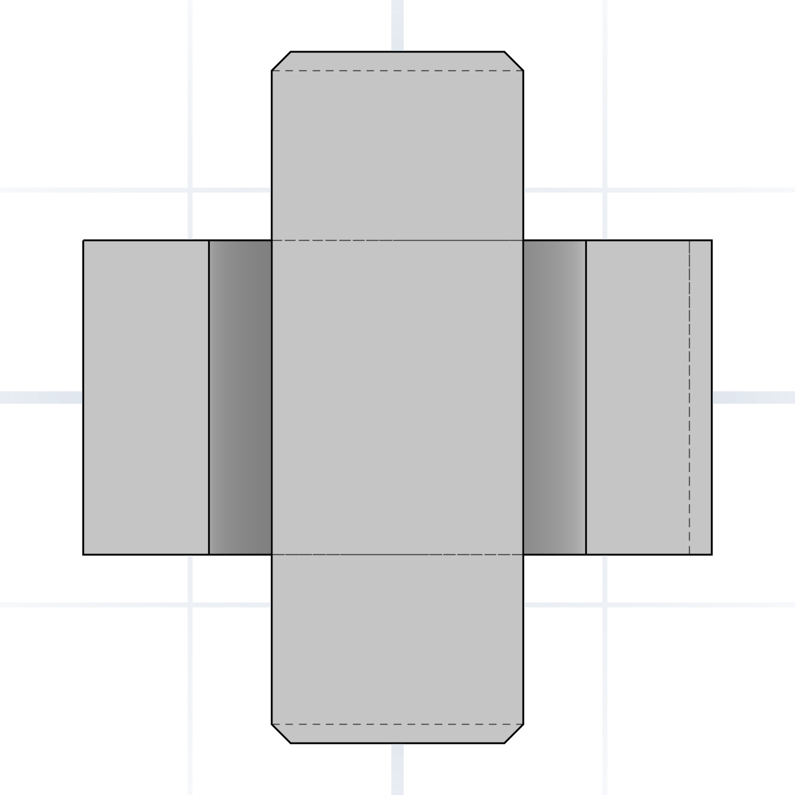
Rotates or moves with a visible gap. Hinge pins, axles, bolt clearance holes. FDM: +0.5 to +0.8 mm on diameter.
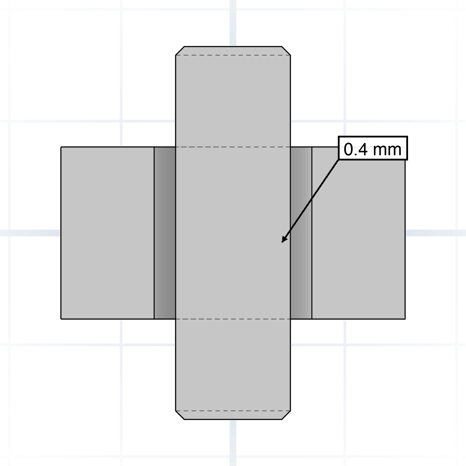
Easy assembly with room to spare. Cable pass-throughs, decorative covers, snap-on caps. FDM: +0.7 to +1.0 mm on diameter.
Scan for the online tolerance & fit calculator. Values for common printer types, scaled to your part’s size.
Screws and bolts you’ll actually use on a printed project. Naming the head saves the redesign.
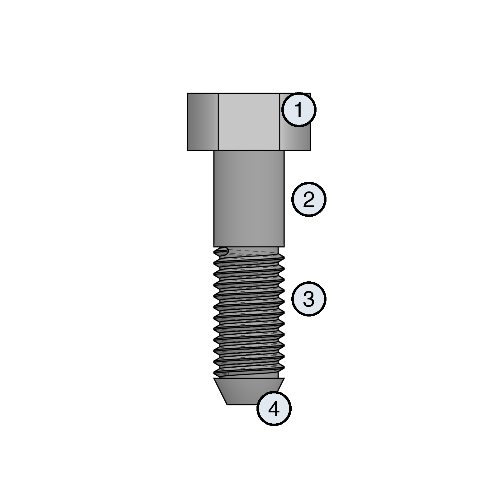
Pointing at the right part of the bolt tells the AI which hardware to clear room for.
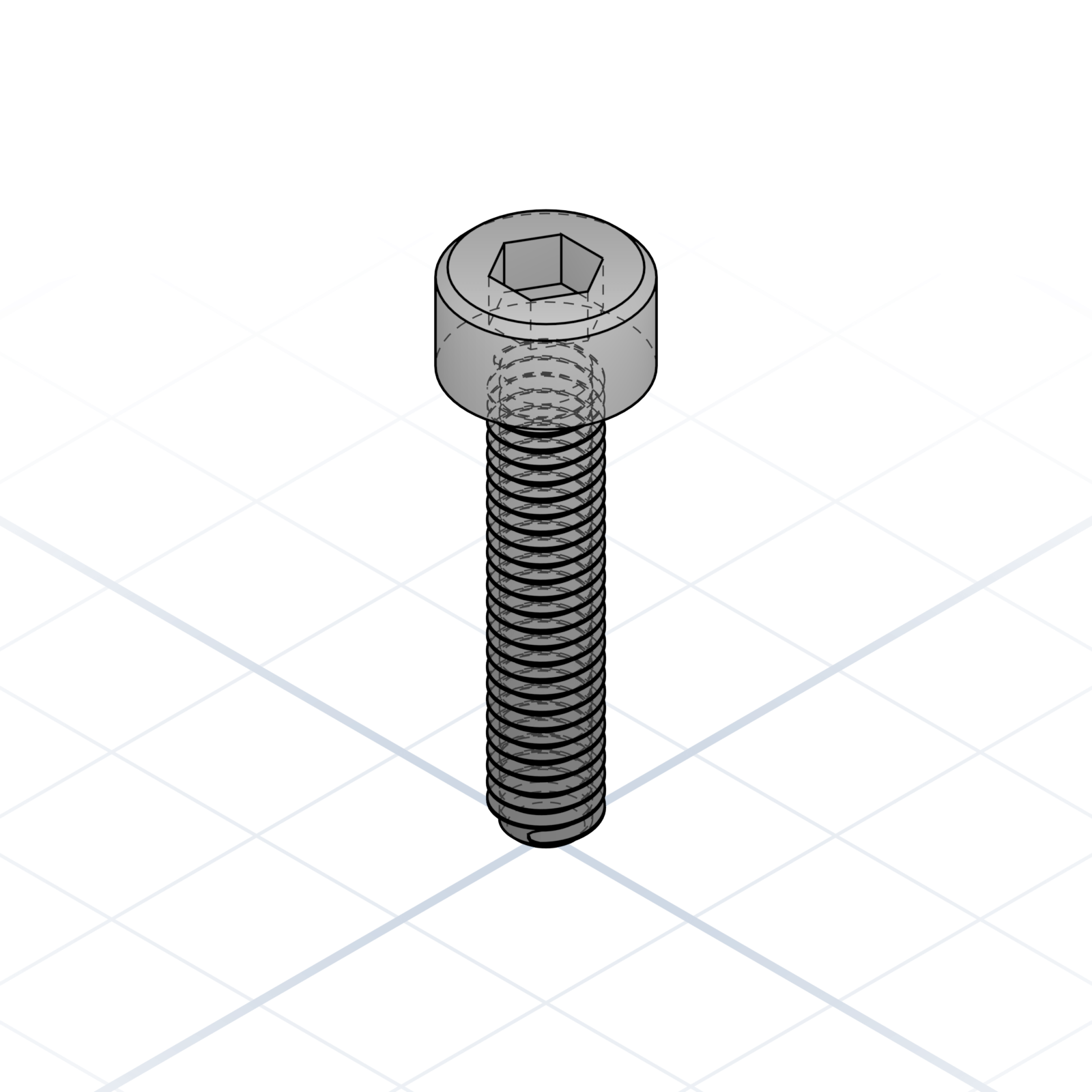
ISO 4762 / DIN 912. The “M3×8” default in most printed projects.
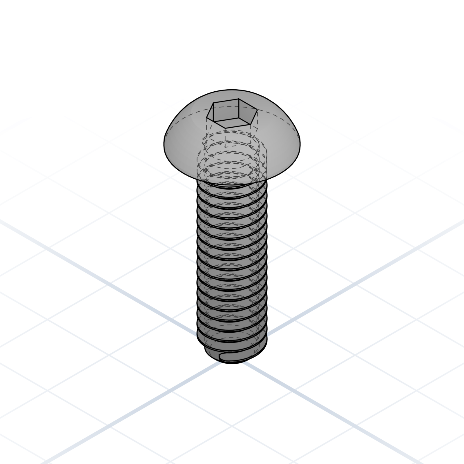
ISO 7380. Lower profile than a cap screw, same hex socket.
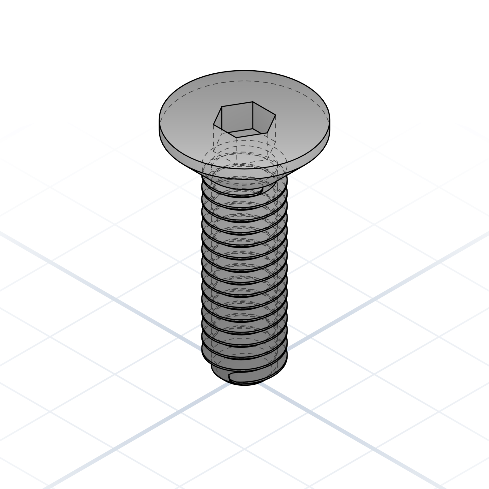
ISO 10642 / DIN 7991. Sits flush in a chamfered hole.
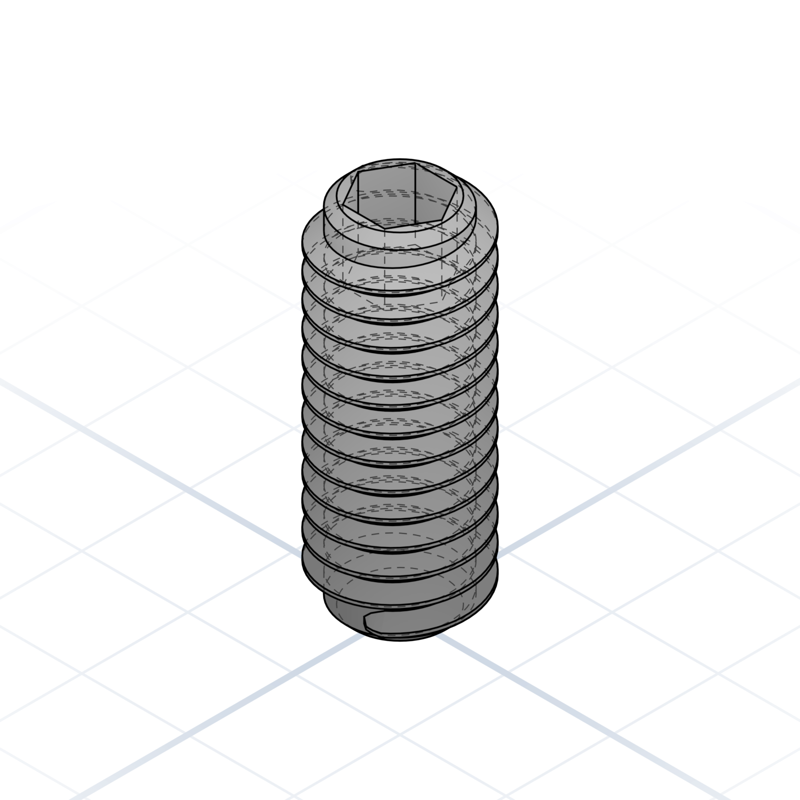
Headless, threaded full length. Holds pulleys on shafts.
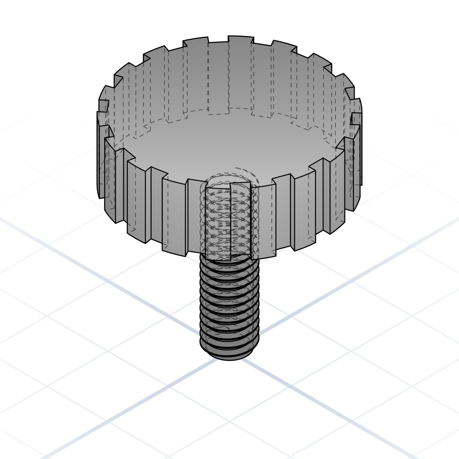
Knurled head, tightened by hand. Good for tool-free assembly.
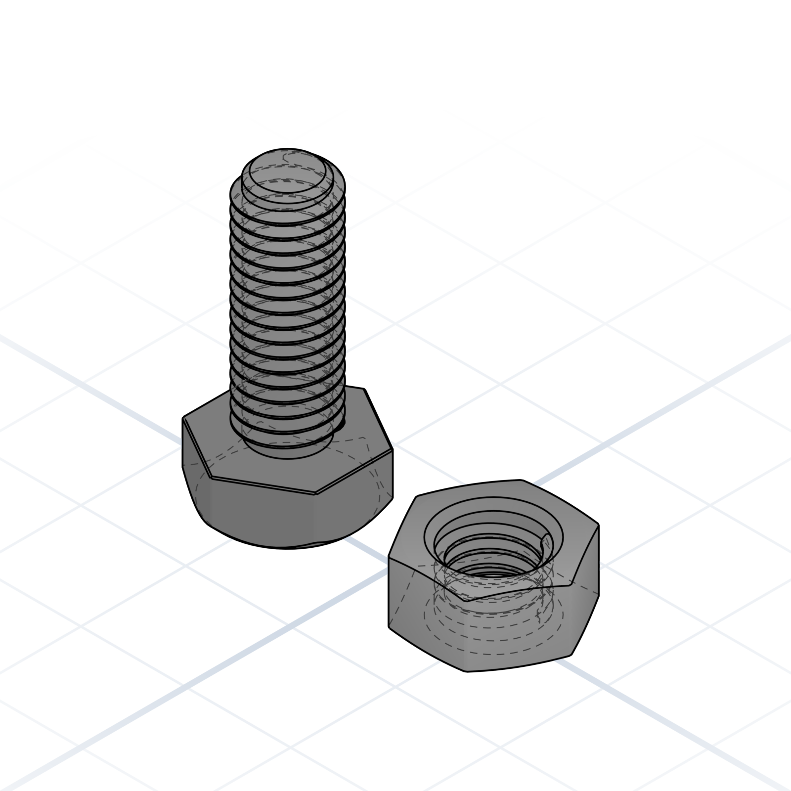
M2–M3 come out as ridges or blobs, so don’t use them. M4–M5 hold light loads; M6 and up are reliable. Very large threads work for clamps and vises. Print the screw and nut standing up.
How you get a thread into printed plastic. Get the technique right and the screw holds for years.
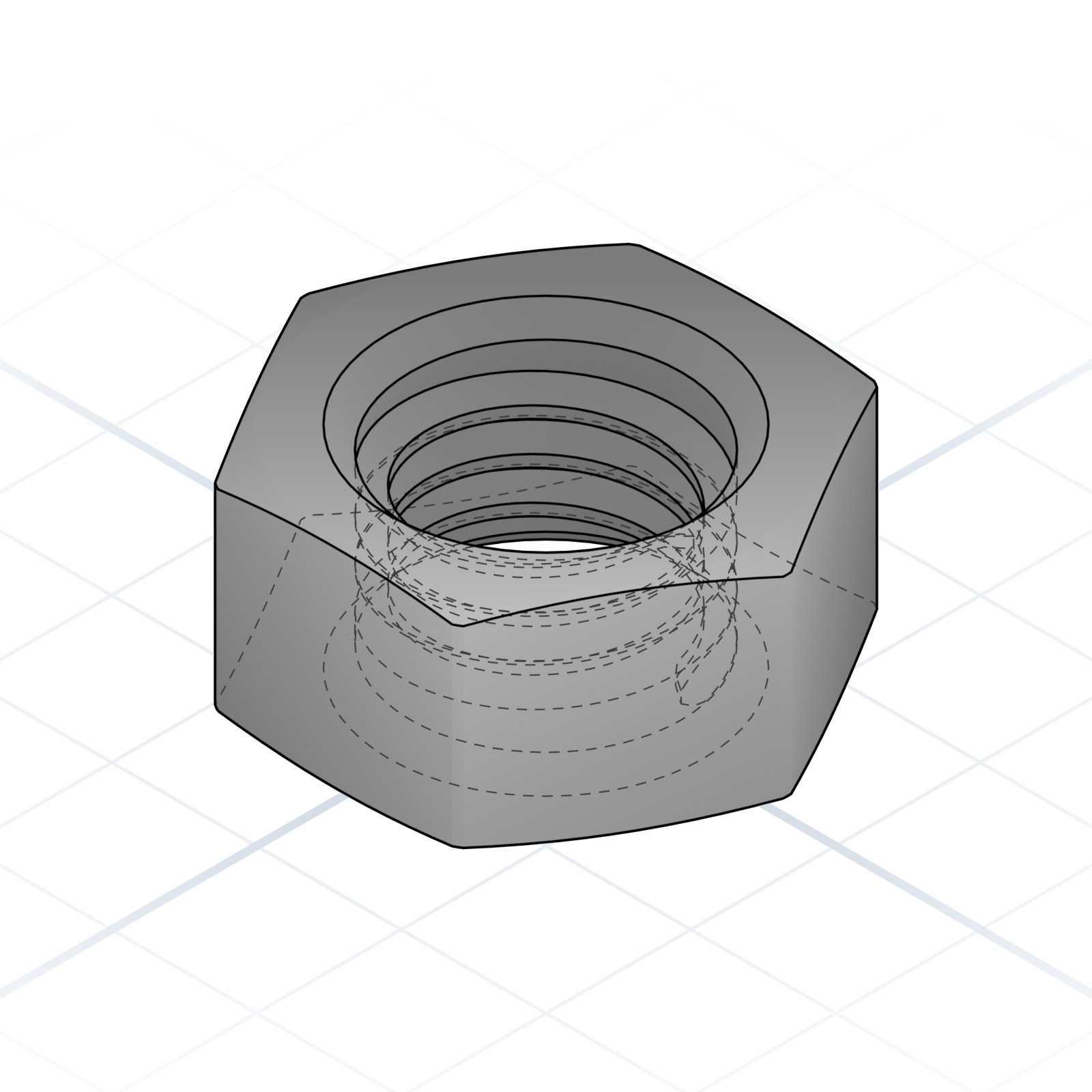
DIN 934 / ISO 4032. The default unless you say square or T-nut.
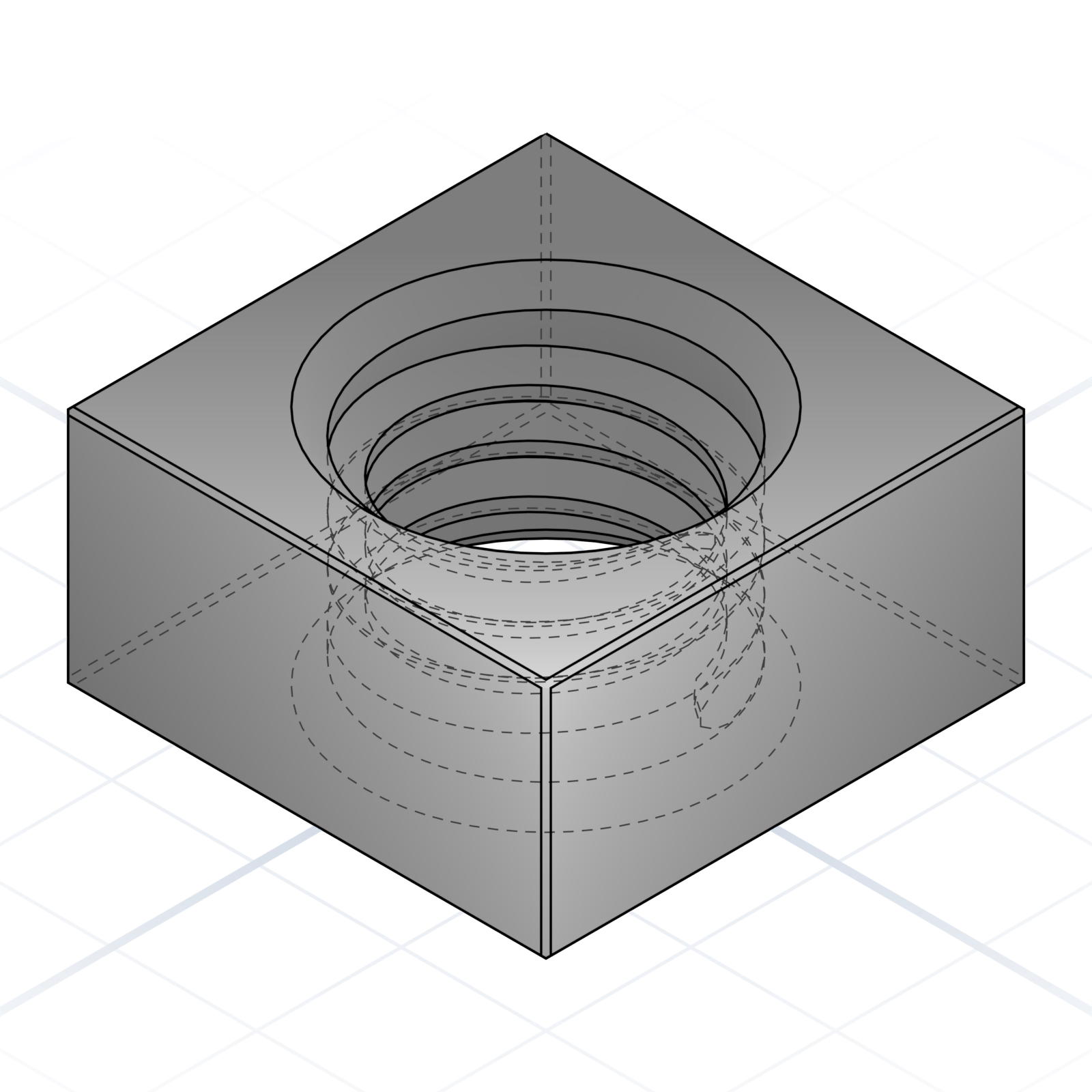
Captive in a square pocket. Good when the back is unreachable.
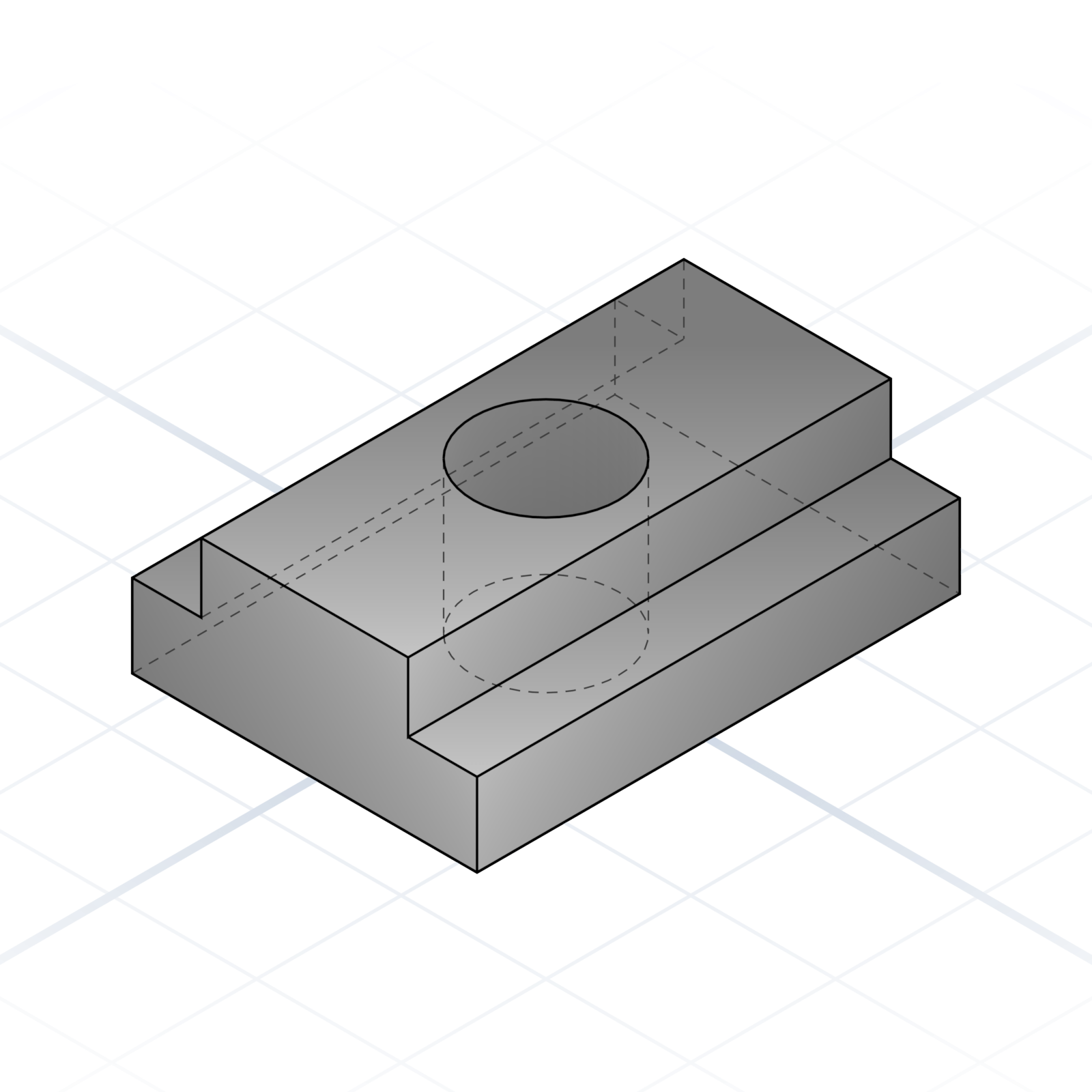
Drops into 2020 / 3030 aluminium extrusion slots.
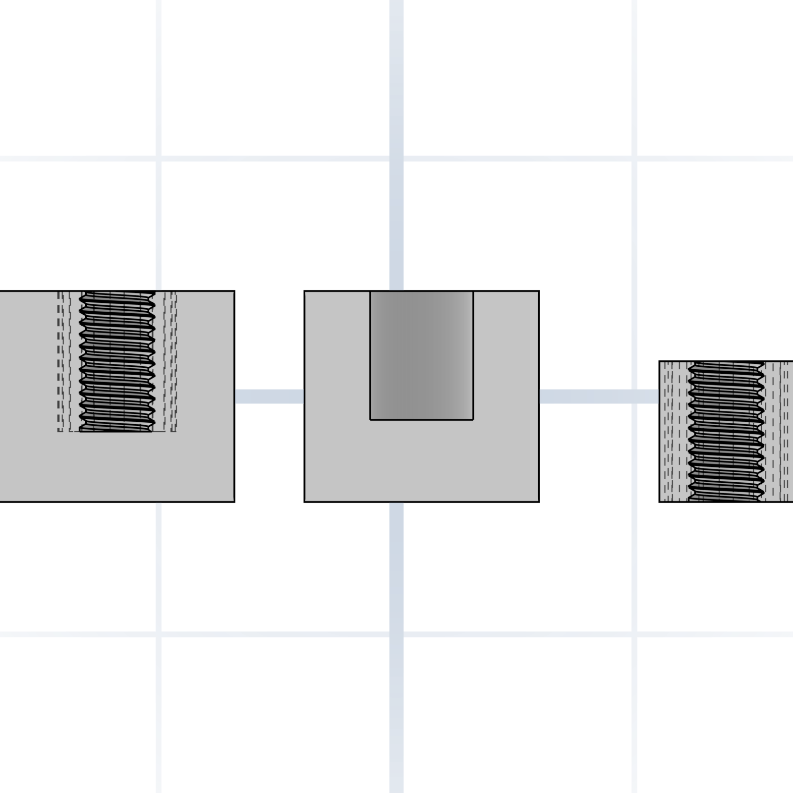
A soldering iron melts it into a printed boss. Strongest option for repeated screw use.
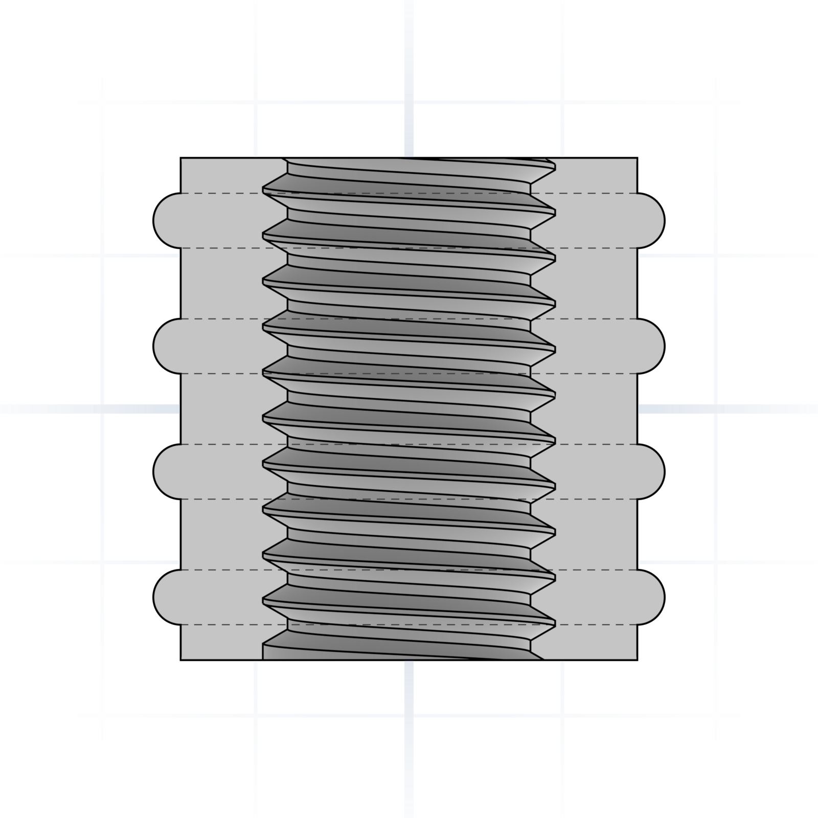
Pressed in cold. Knurled outside grips the plastic.
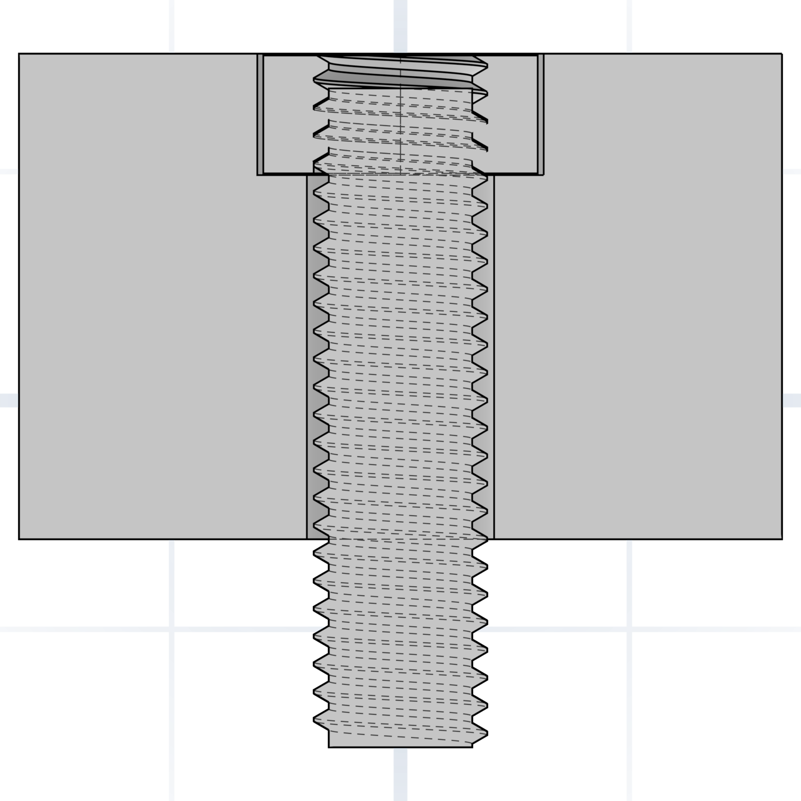
A hex pocket printed into the part. Drop a standard nut in, screw from the other side.
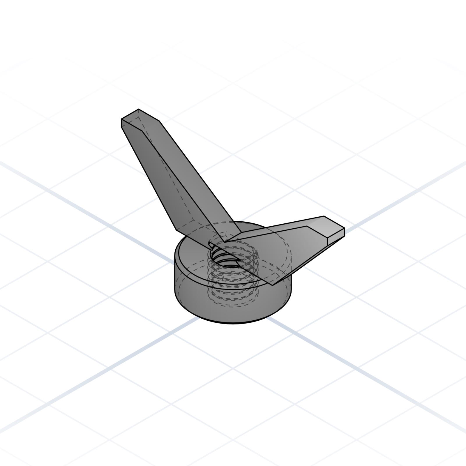
Tightened by hand. Good for parts that get opened often.
Scan for tap drill, clearance hole, and heat-set pilot sizes from M2 to M16, plus head dimensions for socket caps.
How printed parts attach to each other. These hold up without glue when the geometry is right.
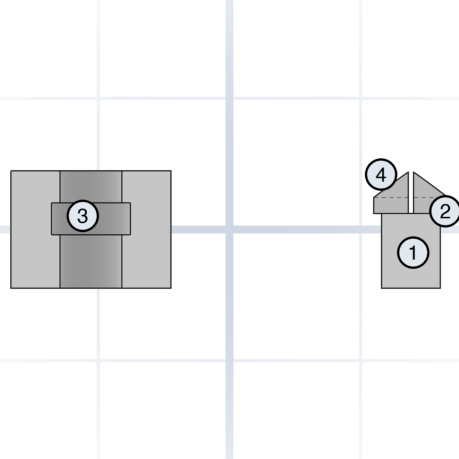
Specify each piece and the AI gets the bend right. A thicker arm is stiffer; the lead-in makes it easier to click together.
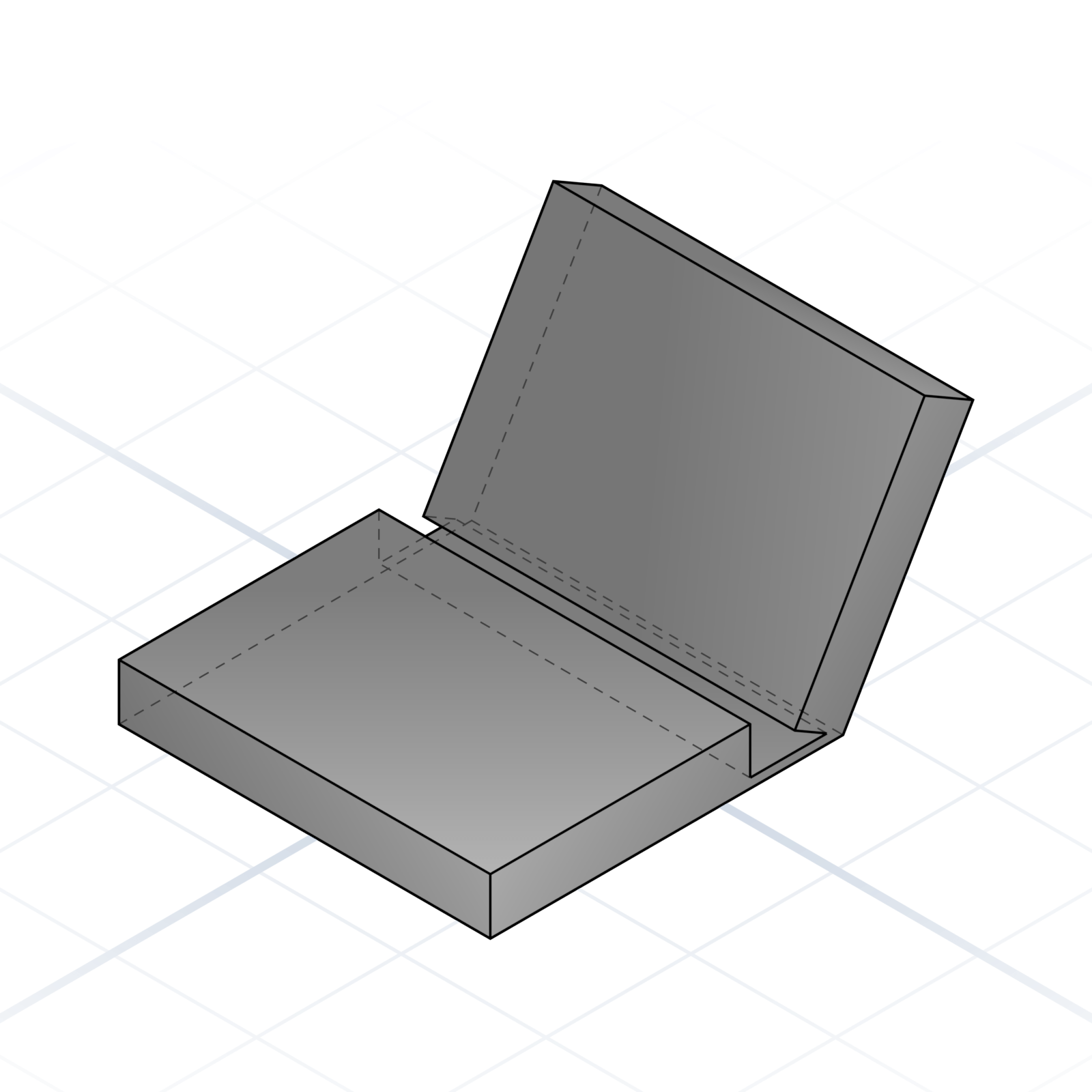
A thin strip (0.3–0.6 mm) that flexes for thousands of cycles. Orient the layers across the hinge, never along it.
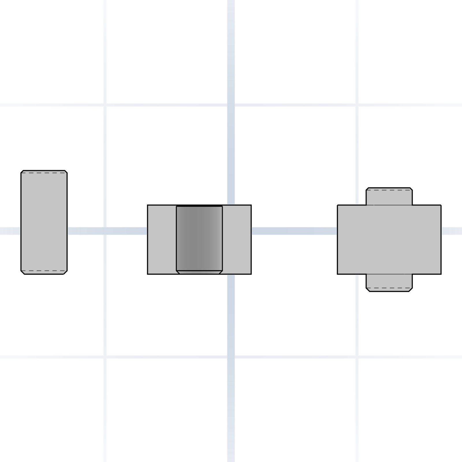
Model the hole at the shaft’s size (±0.1 mm on FDM). Crush ribs make it grip reliably. Add a chamfer to both parts.
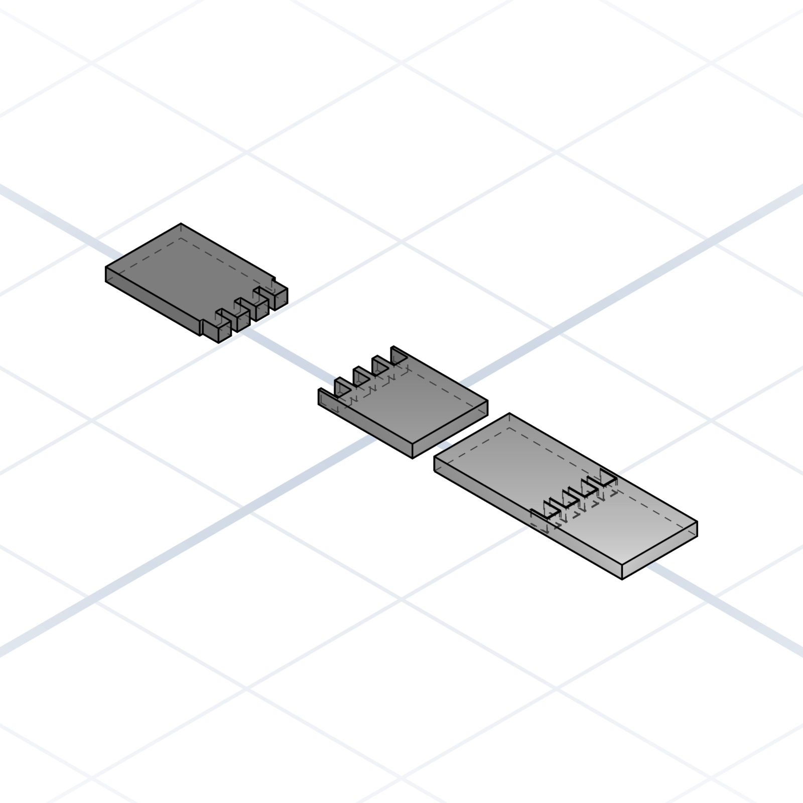
A tab on one part drops into a slot on another. Cleanest joint for flat panels. Lock with glue or a screw.
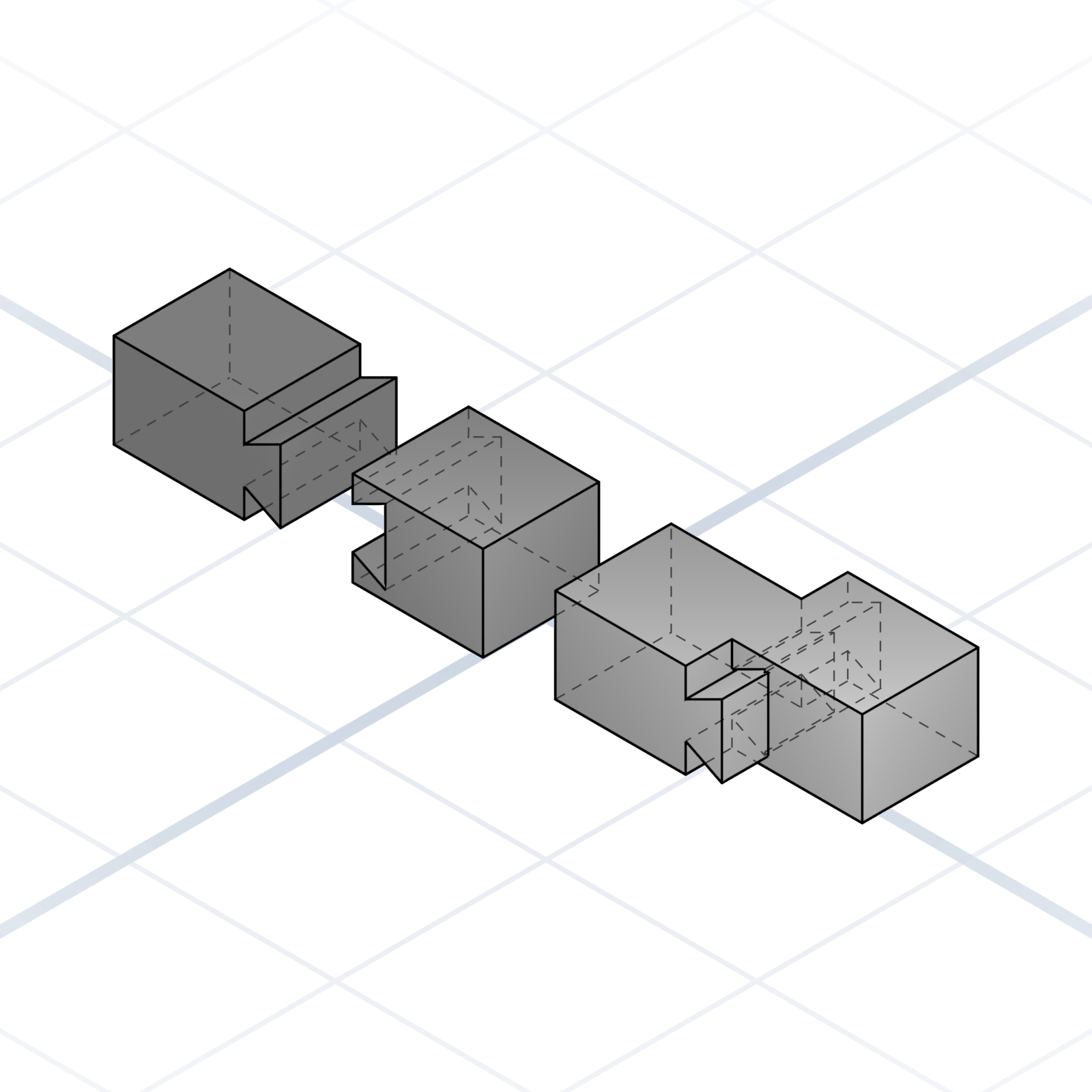
Trapezoidal profile that slides together. Self-aligning and captures one axis. Use 7–10° flare.
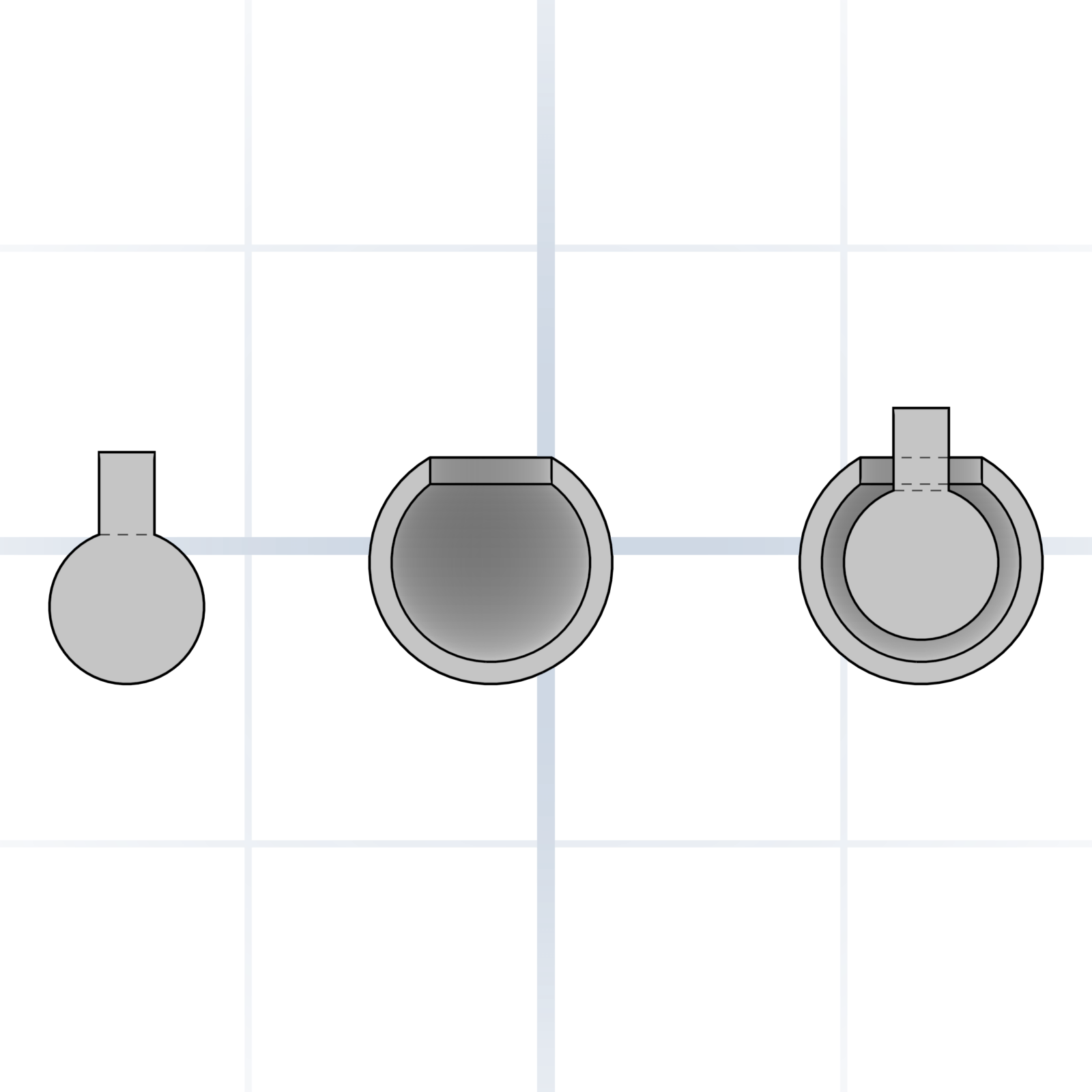
Spherical ball in a partial socket. Print the socket about 0.3 mm larger so the ball rotates freely.
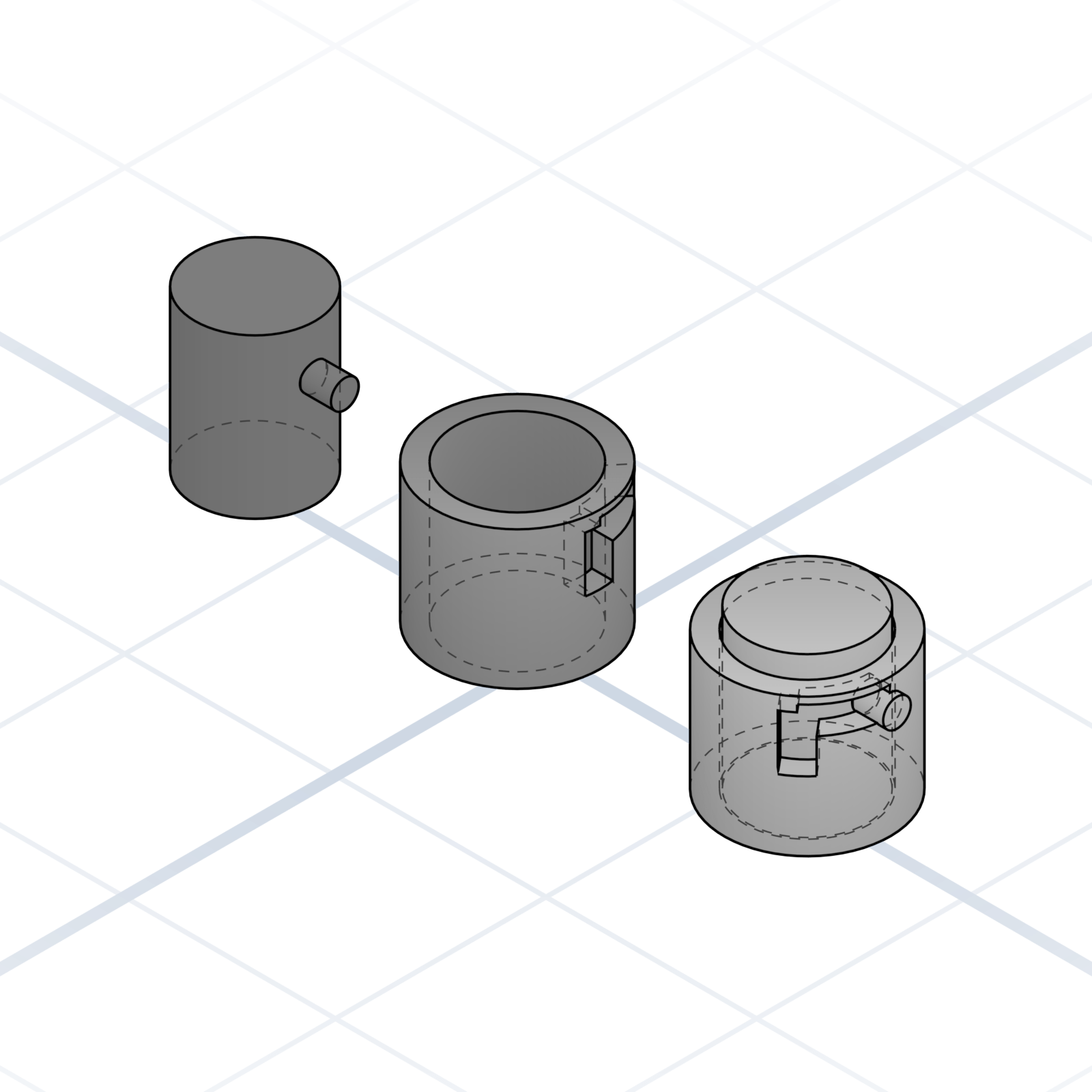
L-shaped slot. Push in, twist 90° to lock. The standard lid joint when threads are overkill.
Ready-made joins that snap, slide, or twist printed parts together, no separate hardware needed.
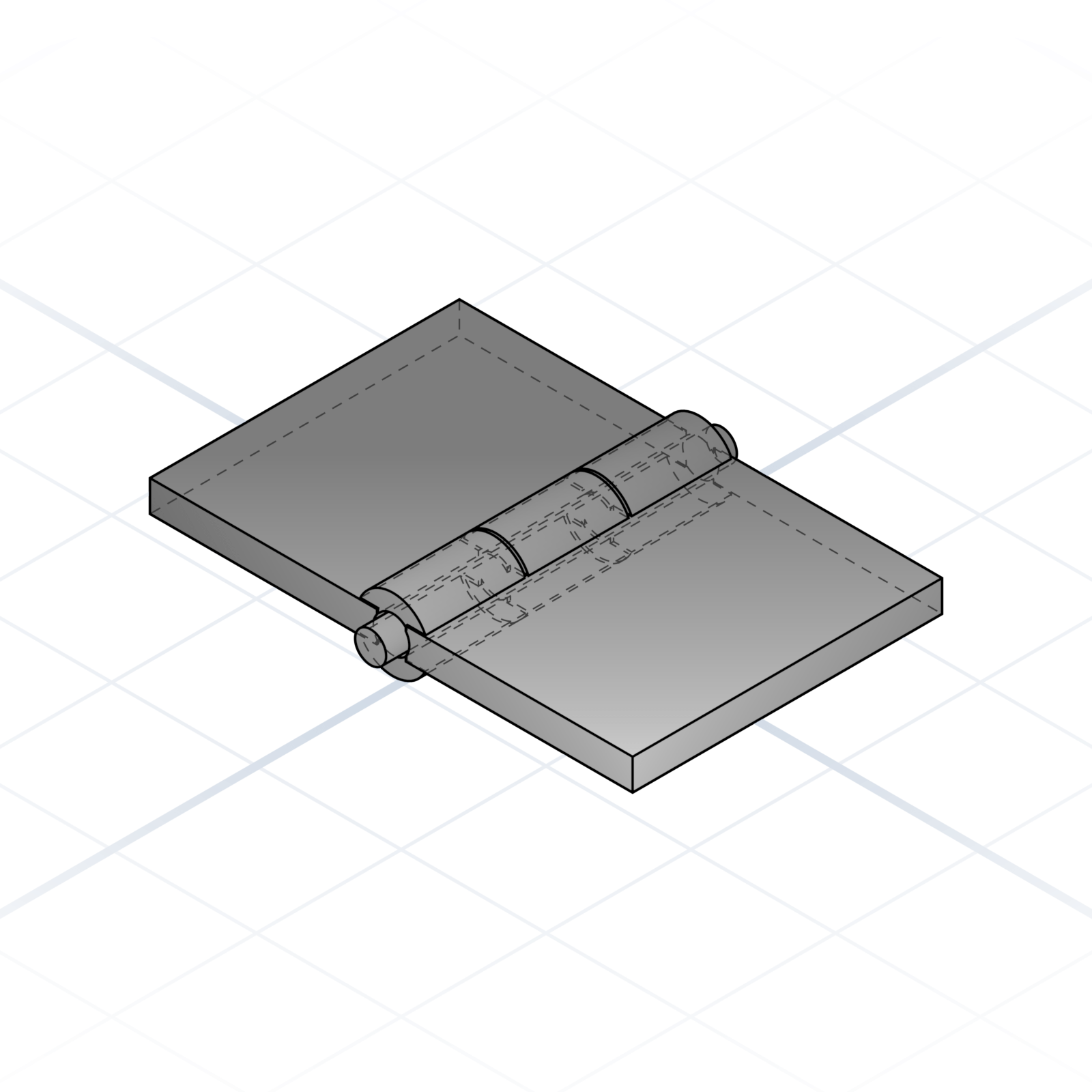
Two leaves with alternating fingers (knuckles) that wrap around a pin. Print both leaves flat, slide a 1.75 mm filament offcut or steel rod through as the pin. 4 mm knuckles print cleanly without supports.
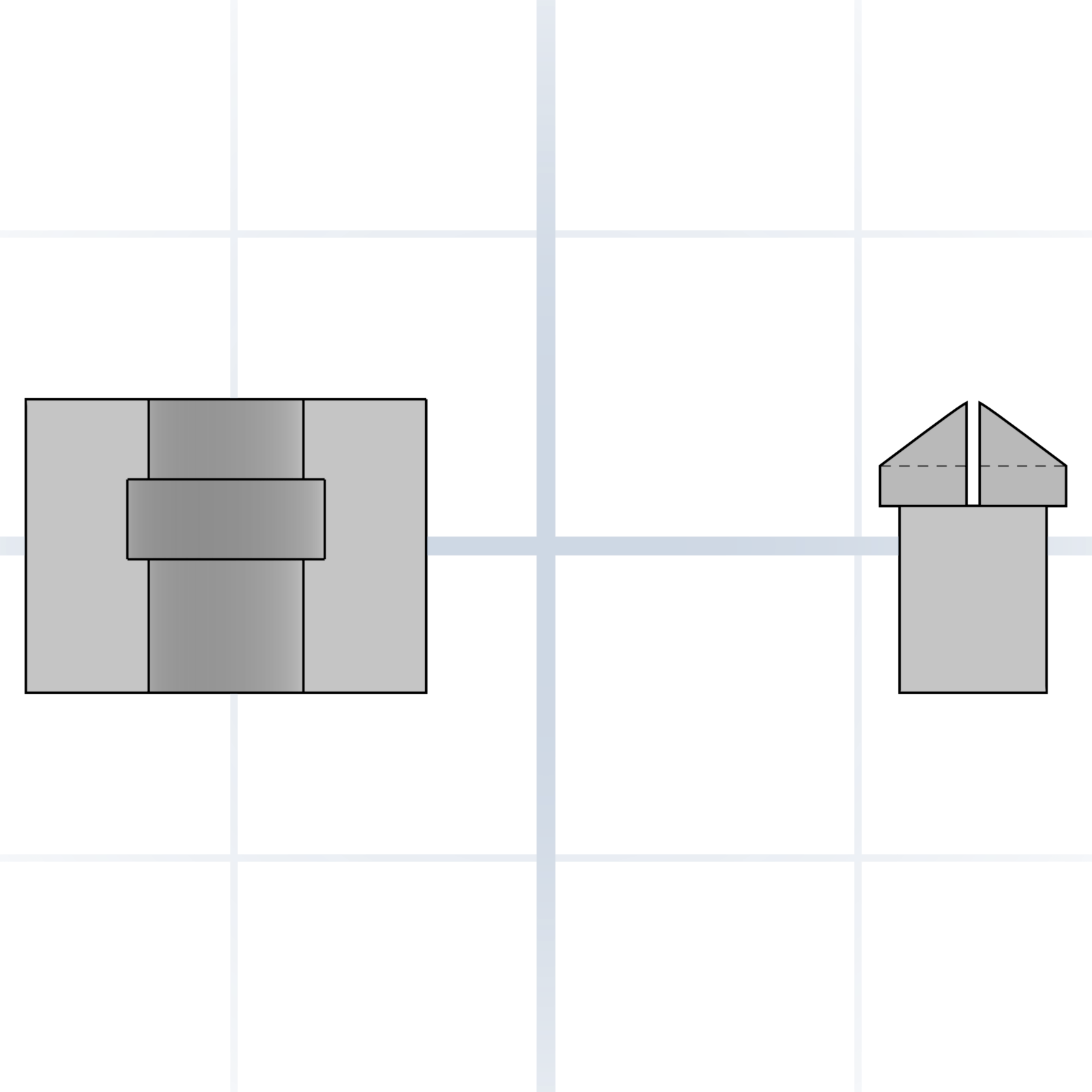
A pin that pushes into a socket and clicks in place. The pin tip is split into four flexible petals that squeeze together on entry, then spring back behind a rim inside the socket. No screws needed.
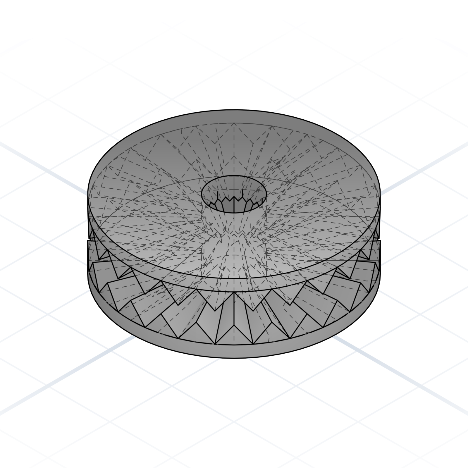
Two discs with matching radial teeth that lock together when clamped. Tighten a bolt through the centre; loosen, turn to a new angle, and re-tighten; it locks in fixed steps (15°, 30°). Used for adjustable arms and joints.
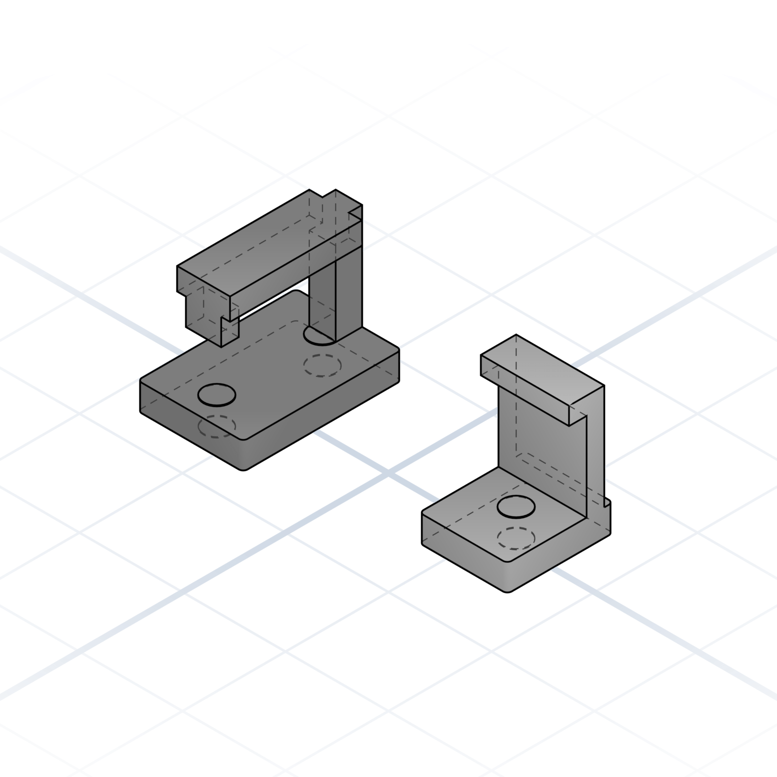
Two printed parts that lock with a slide and a click. A barbed tongue slides into a channel where a living spring snaps over it and holds. Press the spring to release. No screws, good for lids and covers.
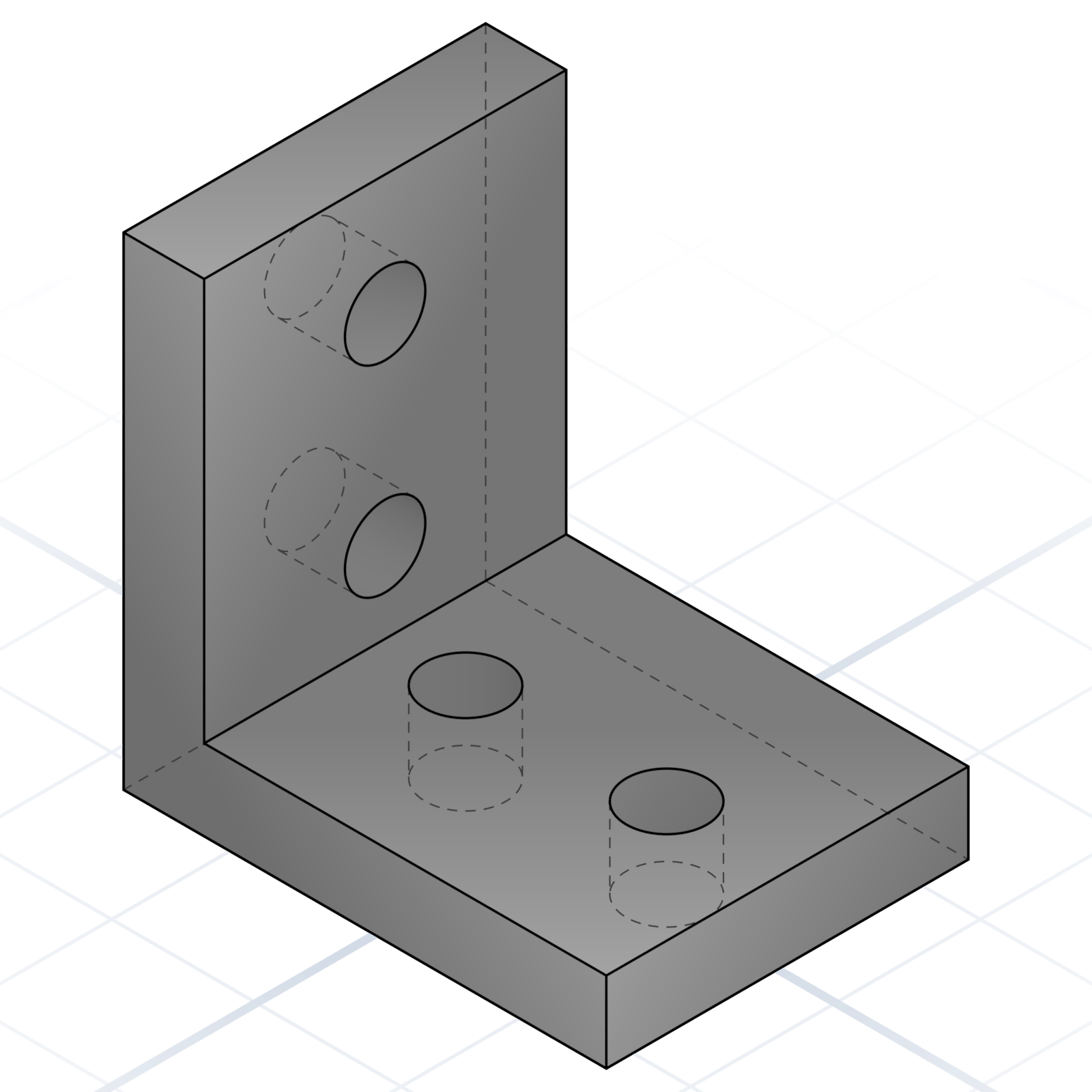
90° L-bracket with mounting holes on both faces. Joins two panels at a right angle. Add a triangular gusset web on the inside if the load reaches kilograms.
Off-the-shelf parts in nearly every printer build, a few euros each from any printer or hardware shop. Name the standard and the model is built to fit it exactly.
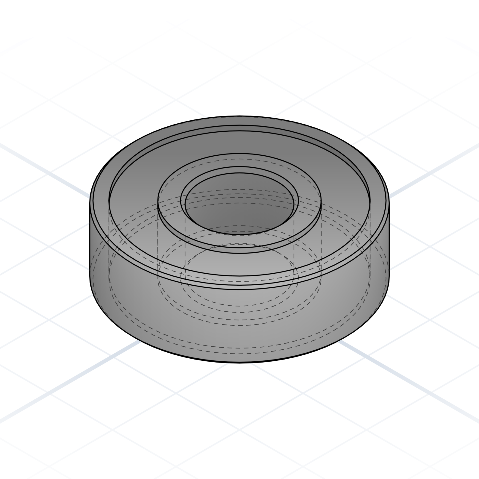
Skateboard bearing, 8 × 22 × 7 mm. Spinners, idlers, friction-fit pulleys.
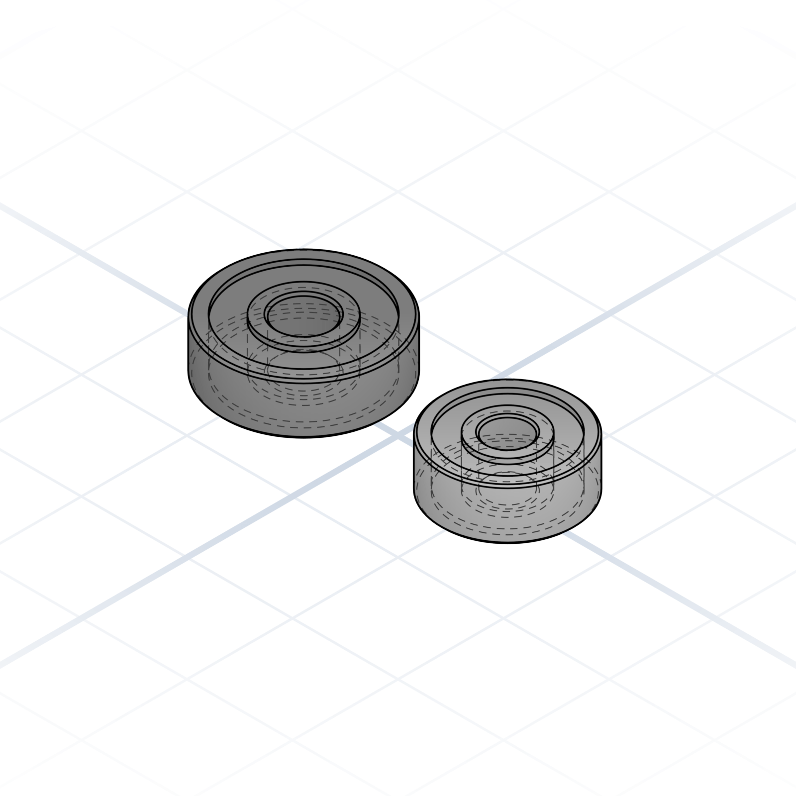
5 × 16 × 5 and 4 × 13 × 5. The small idlers you’ll see in printer kits.
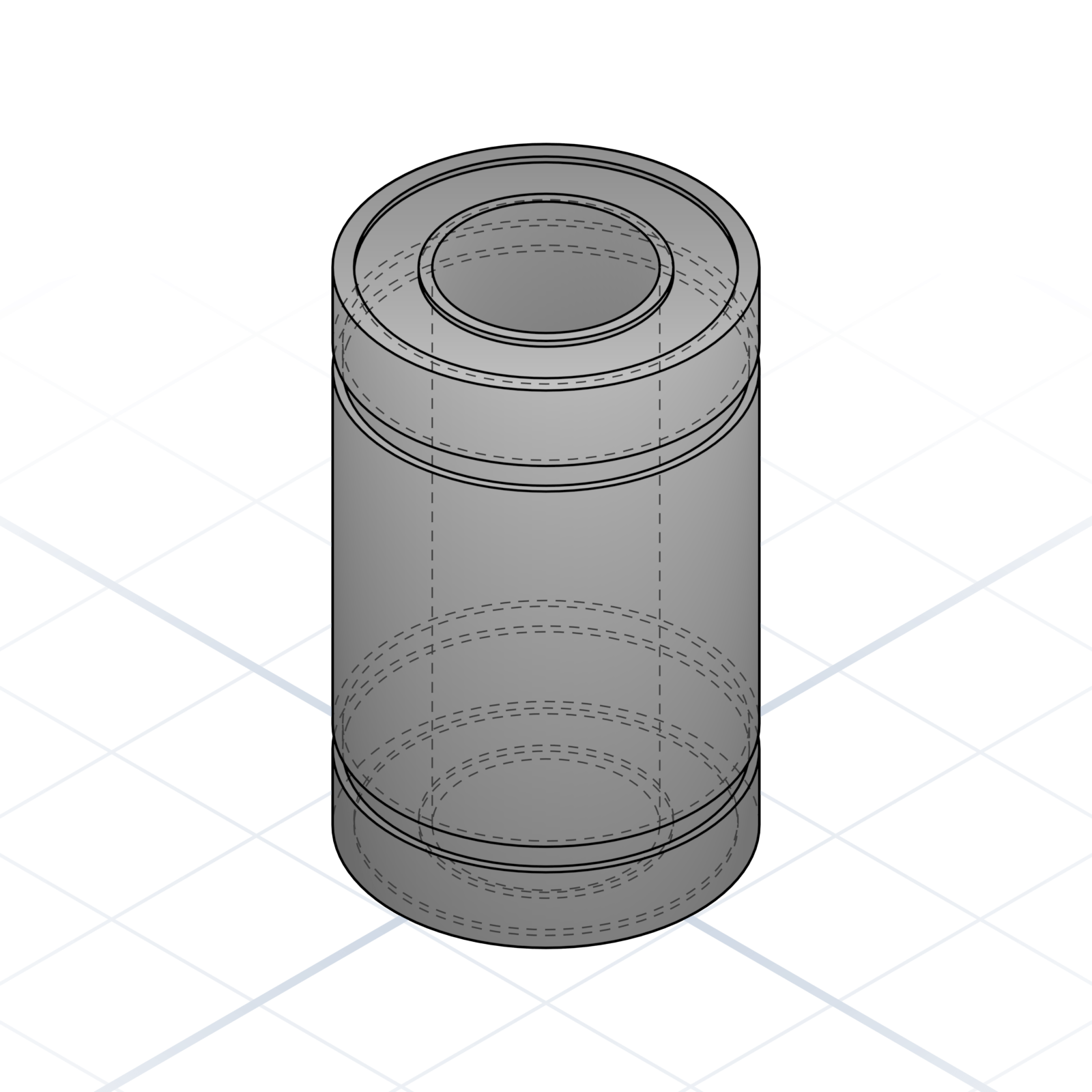
Recirculating ball bearing on an 8 mm smooth rod. The standard linear-motion part.
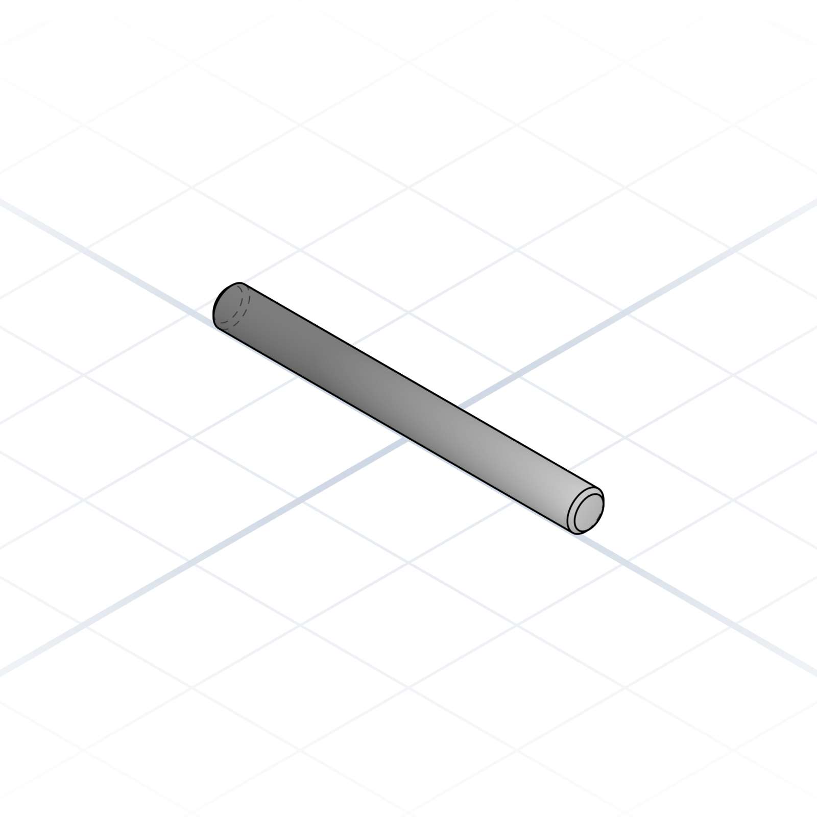
Chromed steel shaft, usually 8 mm. Linear bearings glide on it.
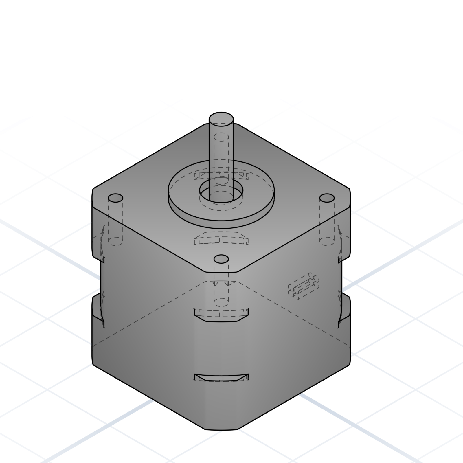
42.3 mm face, 5 mm shaft. Mounting holes on a 31 mm square pattern. Say “NEMA 17 mount” and the holes line up.
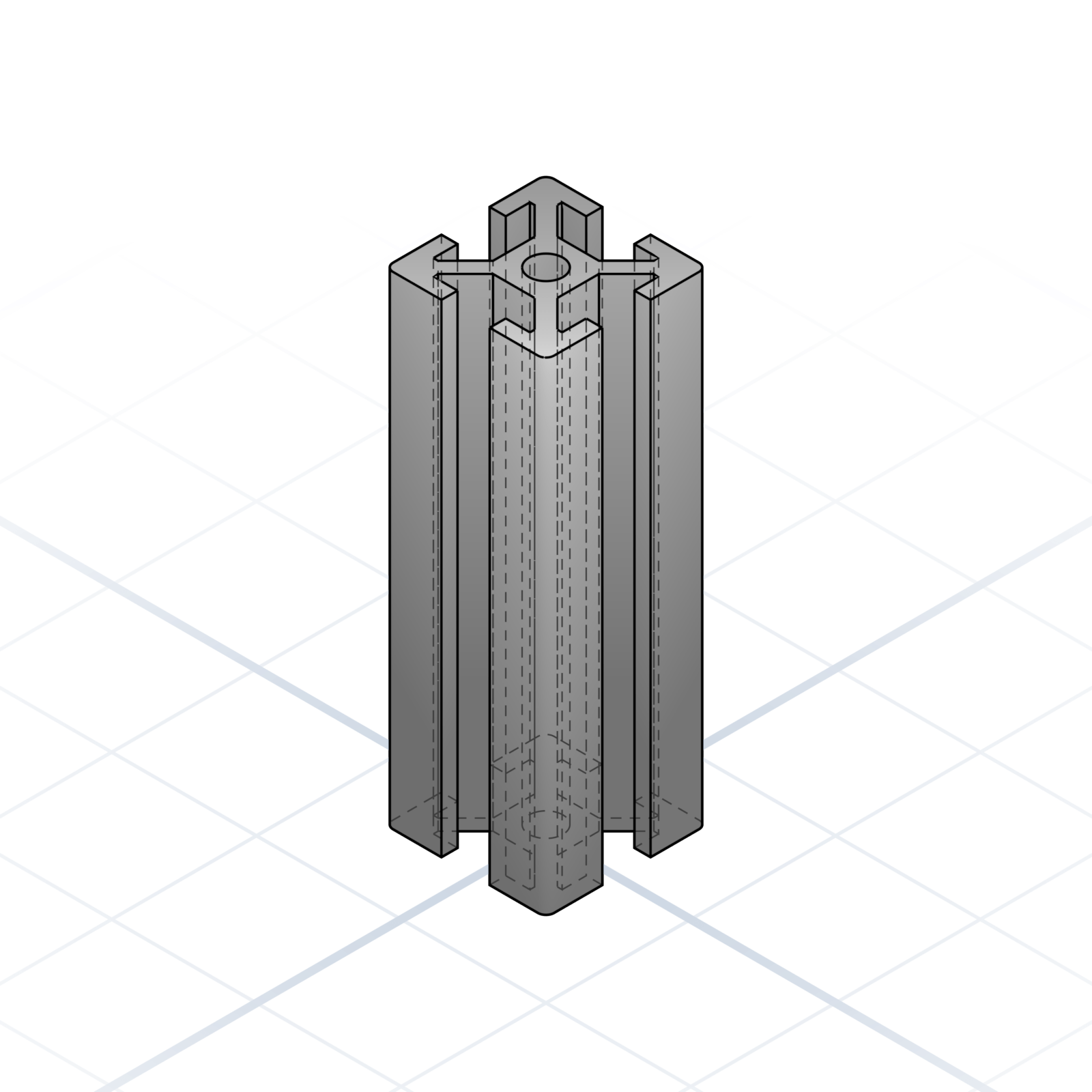
20 × 20 mm cross-section with a 6 mm T-slot. The skeleton of most printer frames.
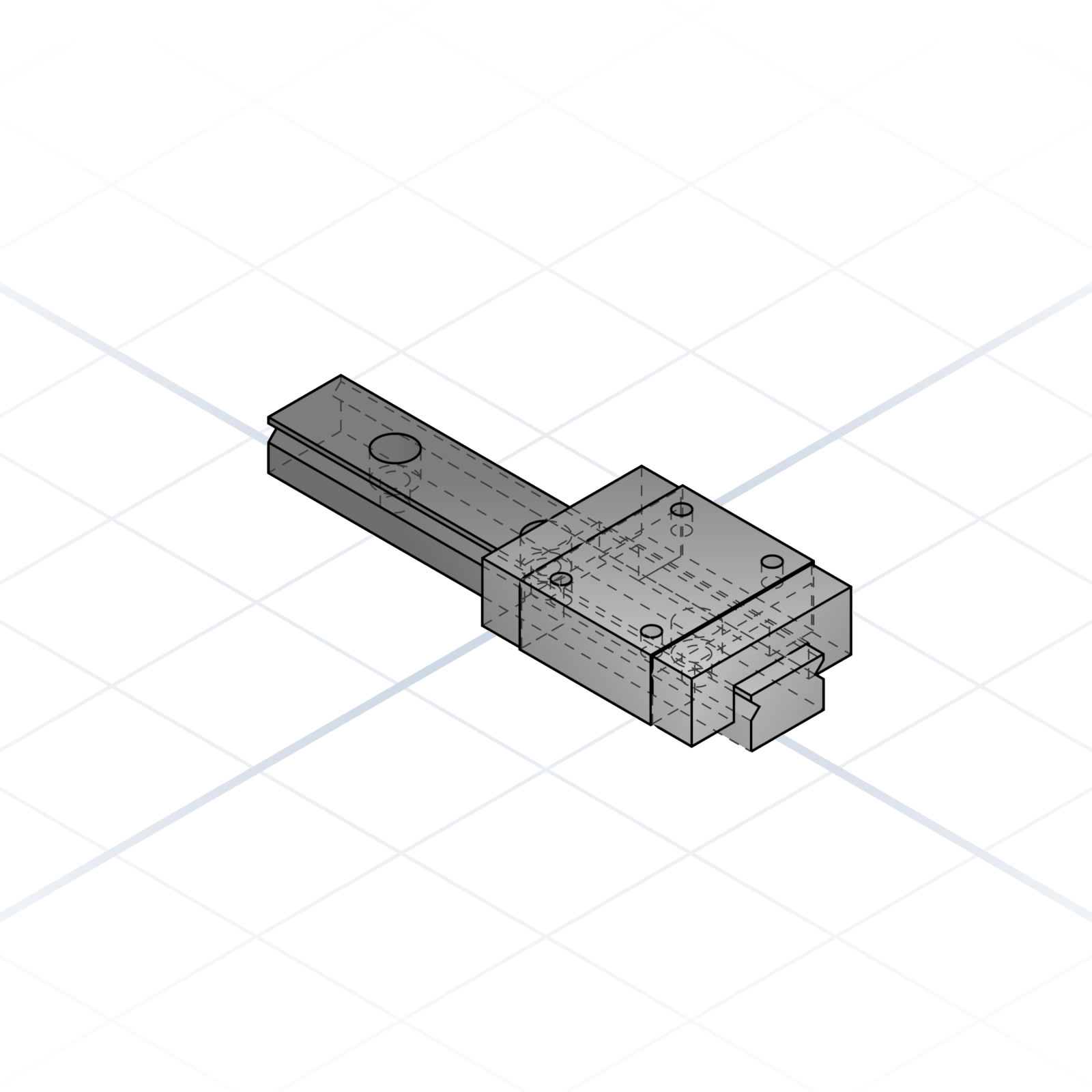
12 mm rail with an MGN12H carriage. Stiffer and quieter than smooth-rod motion.
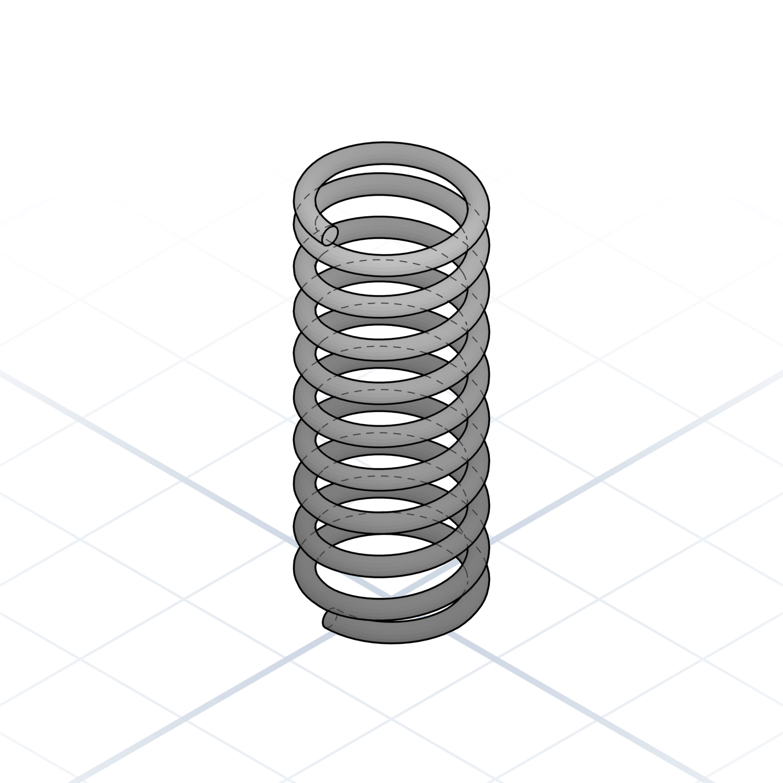
Compression spring, 8 mm across and 20 mm tall. The yellow springs under most common printer beds.
The parts that turn a motor’s spin into straight-line motion, the same belts and screws every printer kit ships with.
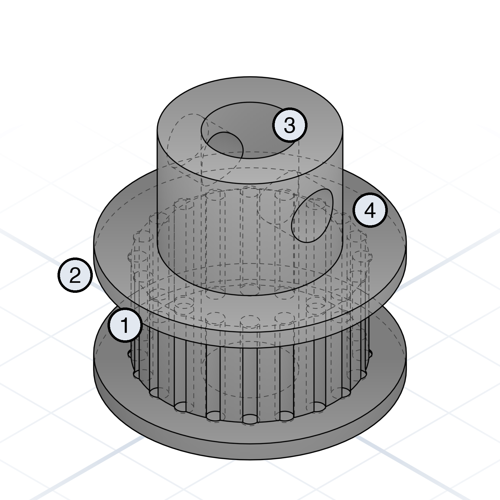
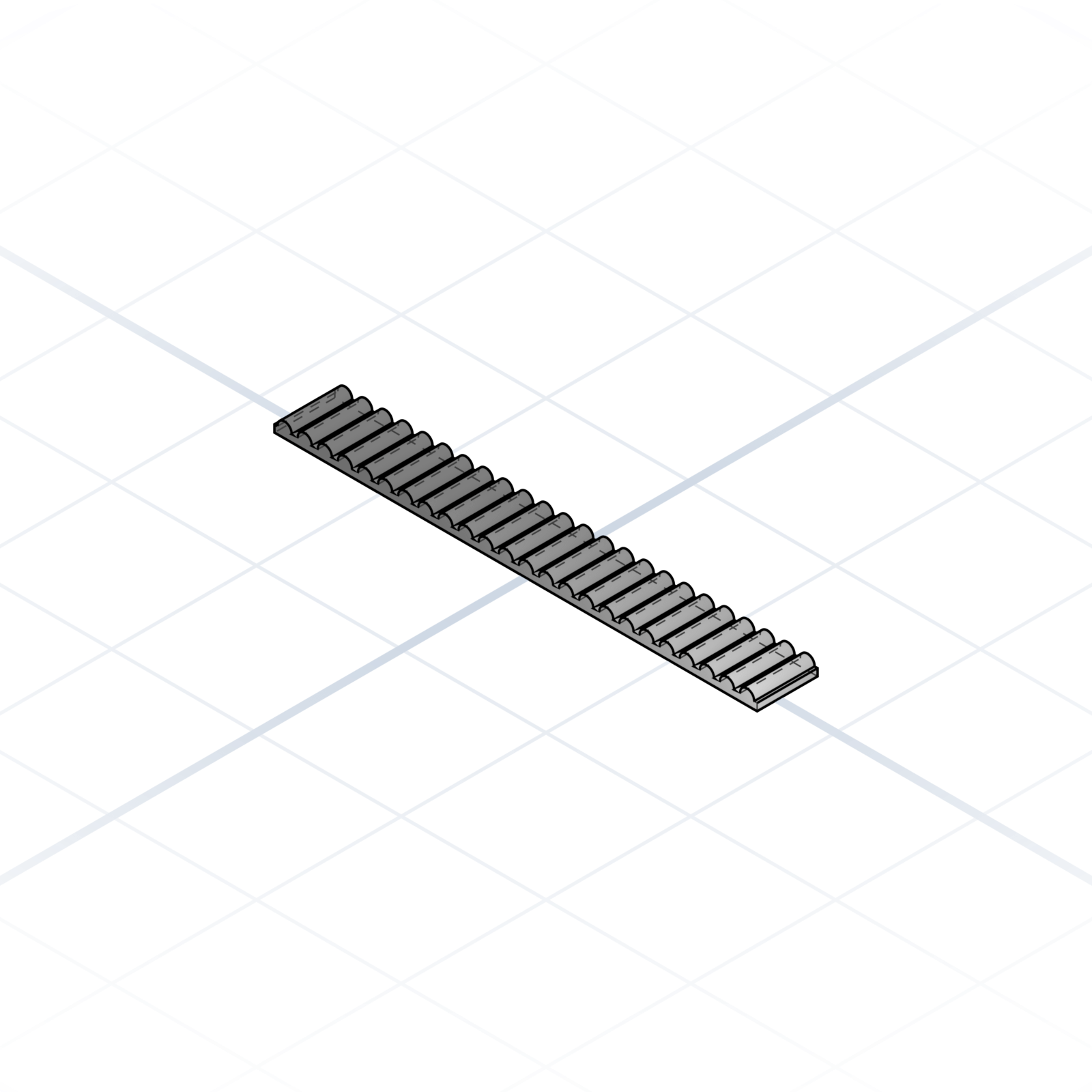
2 mm pitch toothed belt. 6 mm wide is standard, 9 mm for heavier carriages. Loop length matters; open belt is cut to size.
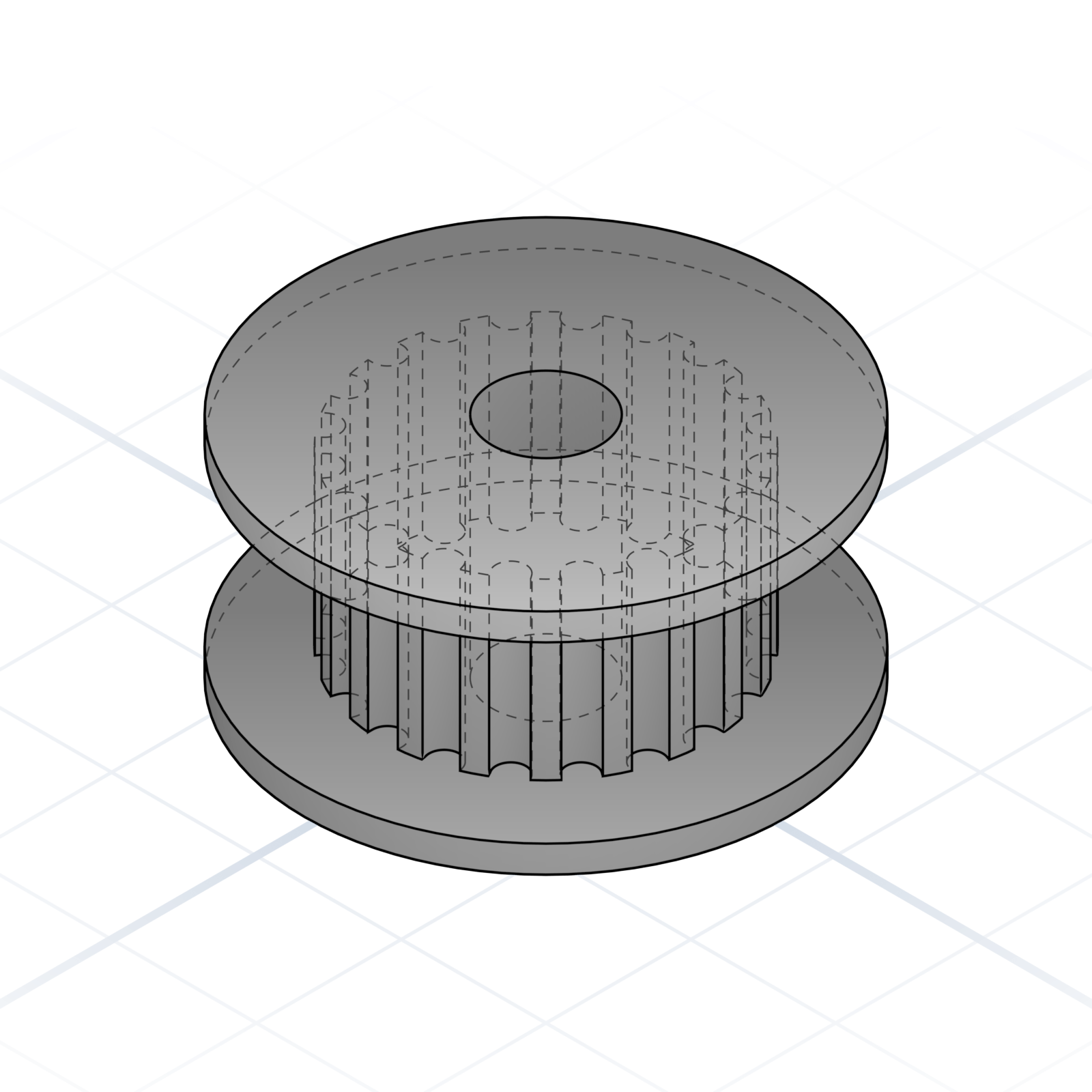
Bearing with a GT2-toothed face. Reverses belt direction without the belt slipping on the wheel.
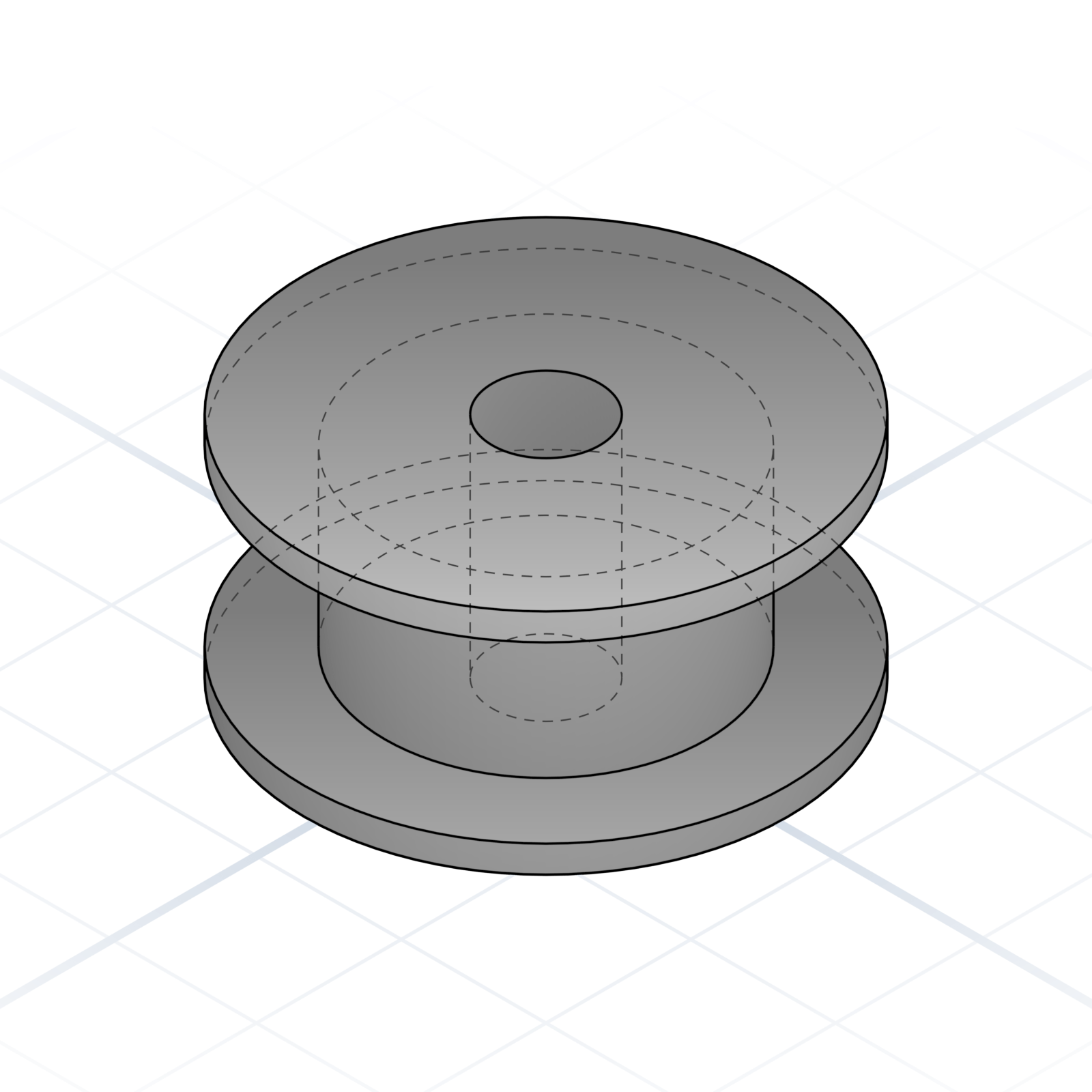
Flanged bearing with a plain face. Used where the back of the belt rides the wheel.
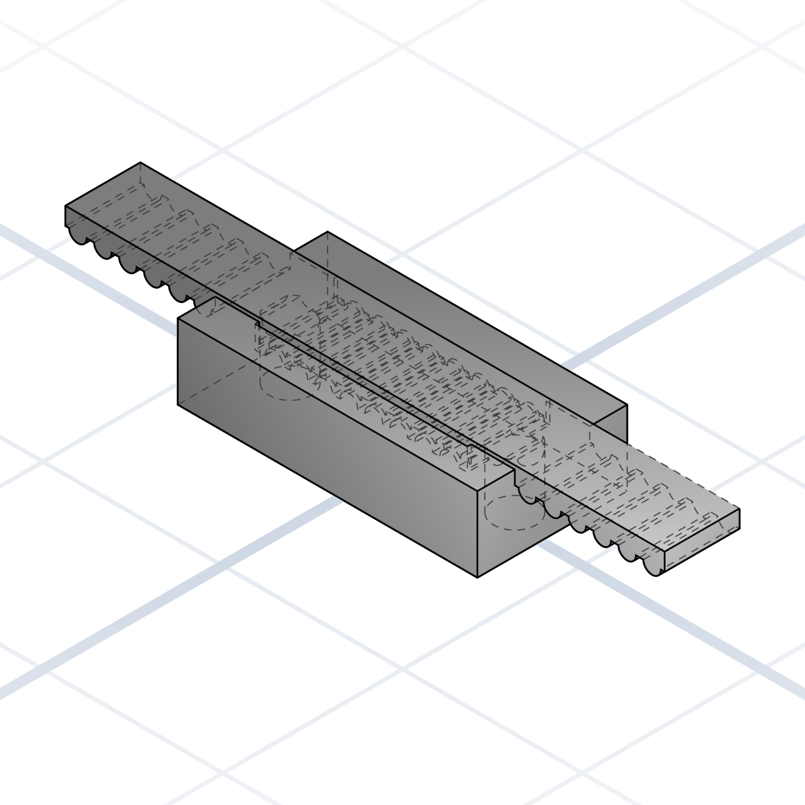
Printed block with a serrated slot that grips a GT2 belt by its teeth. Print the slot teeth at the same 2 mm pitch as the belt, pinch with two M3 screws.
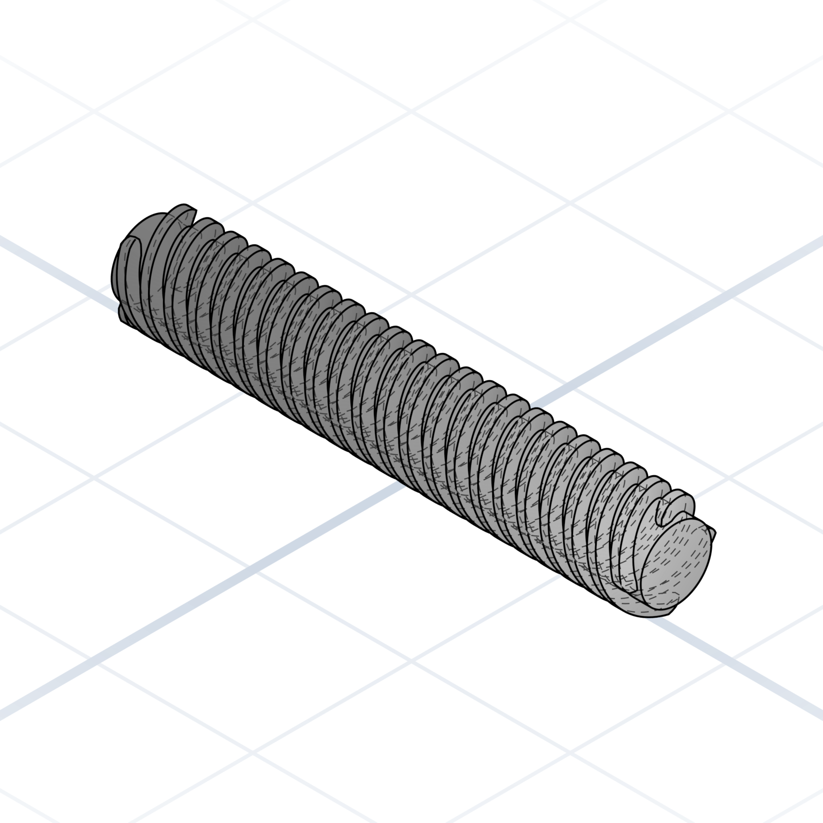
Threaded rod built to drive a nut up and down. It has a coarse thread that moves 8 mm per full turn, so it’s for moving things, not fastening.
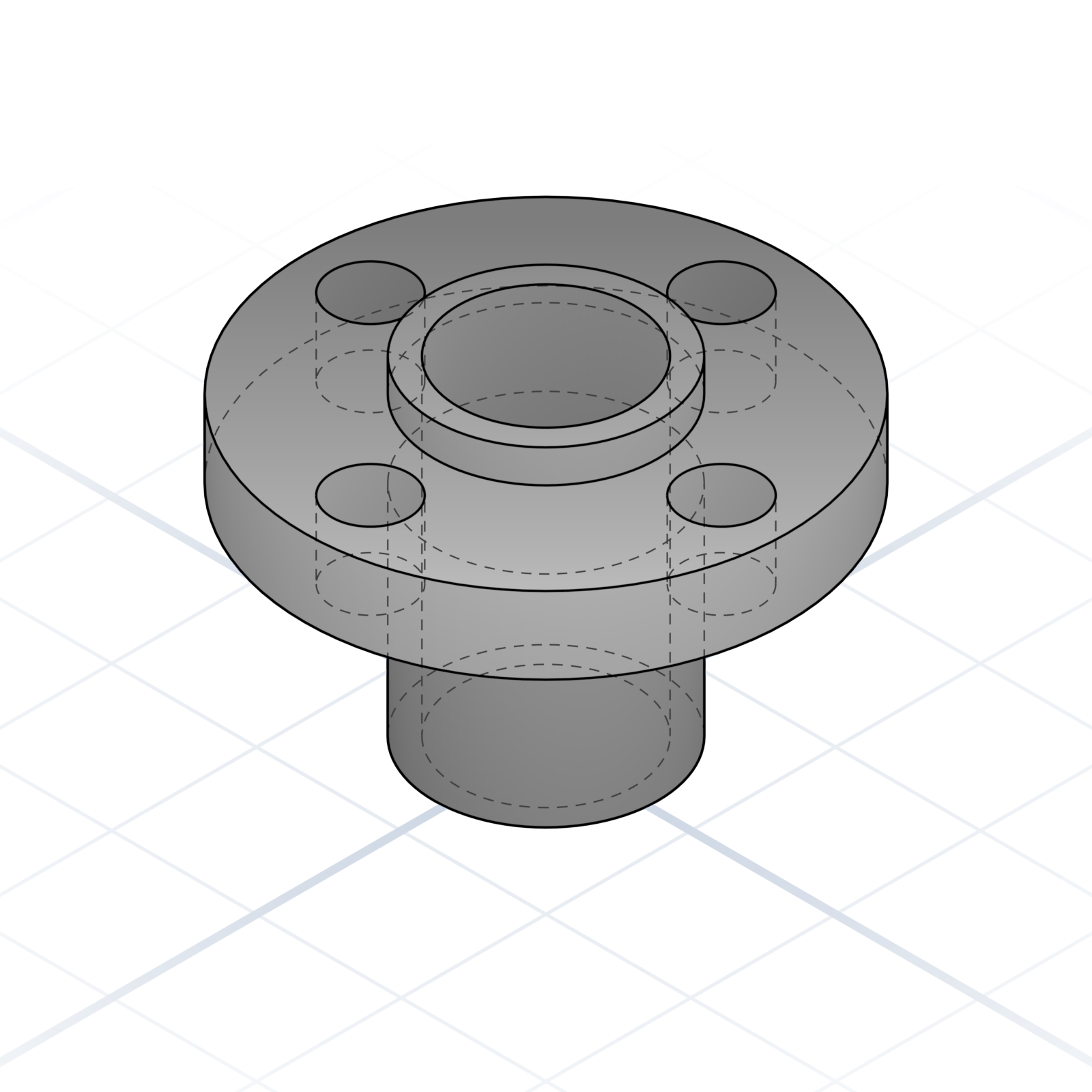
The mating nut for a T8 leadscrew. Bolts to a printed carriage on a 22 mm flange pattern and turns leadscrew rotation into carriage motion. Anti-backlash variant has a sprung second nut for play-free positioning.
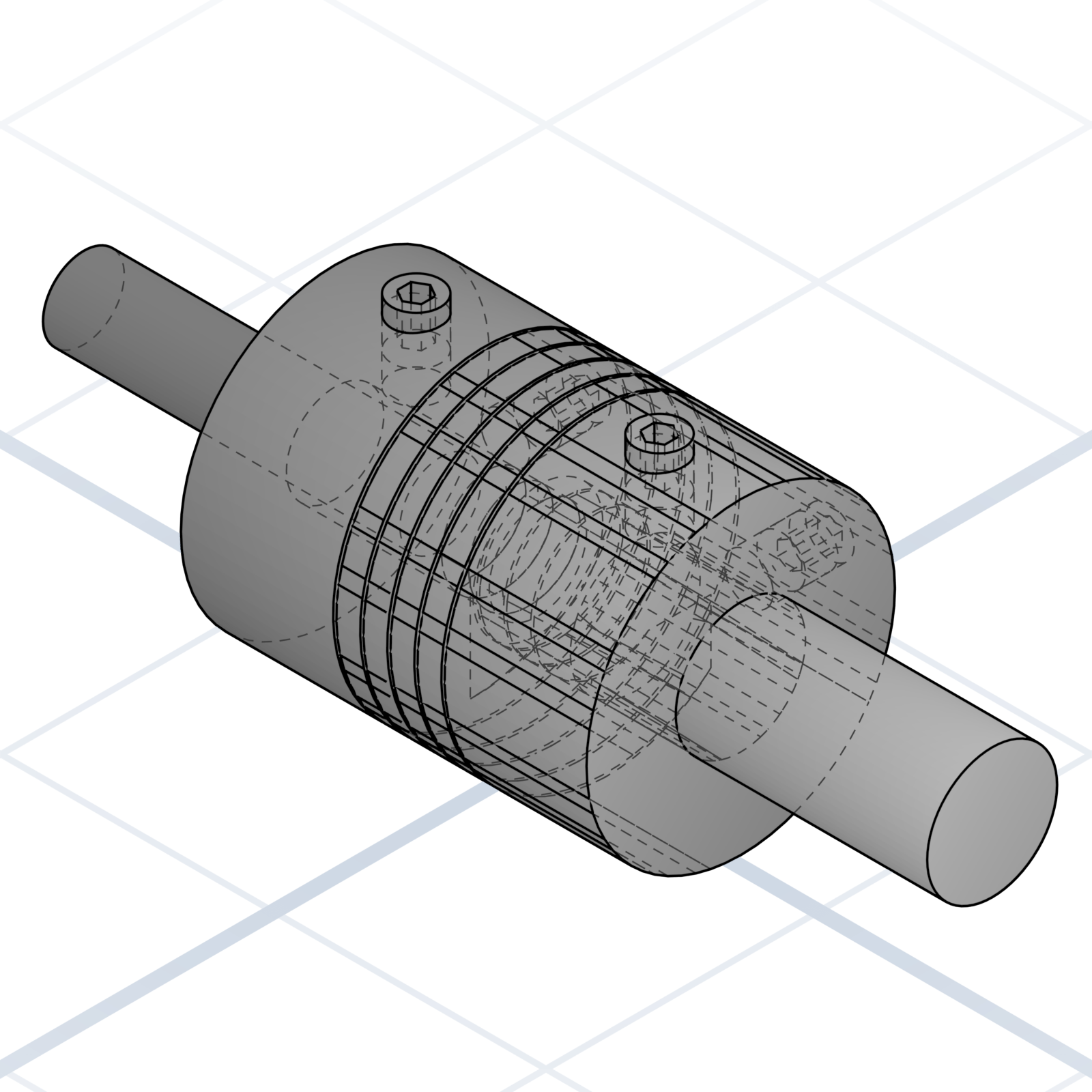
Connects a stepper motor to a Z-axis leadscrew, one shaft in each end. The spiral-cut slots let it bend a little, so a motor that sits slightly off-line from the screw won’t bind or add wobble to the print.
Printing a bracket or enclosure for one of these is one of the most common reasons to design a part at all, whether you’re upgrading your own printer or boxing up an electronics project. Each board has a fixed hole pattern the AI can match by name.
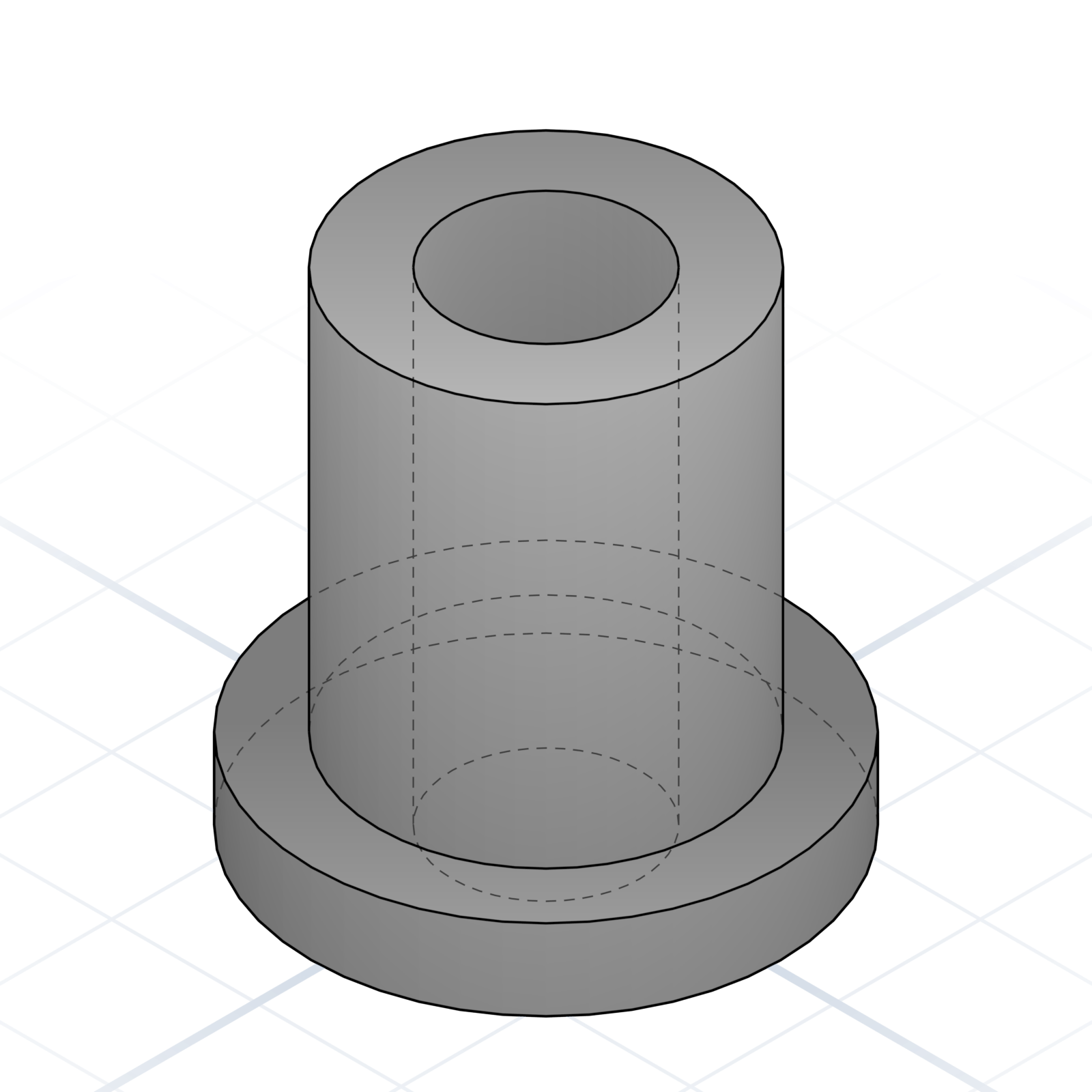
Printed pillar with an M3 heat-set or self-tap hole. State height, hole pattern, and whether the head sinks into a counterbore.
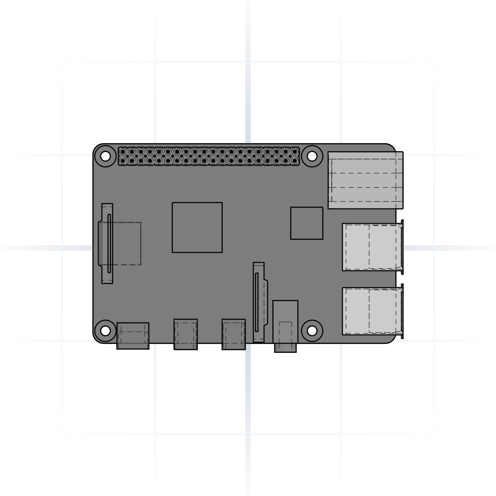
58 × 49 mm M2.5 hole pattern. Say “Pi 4 mount” or “Pi 3 mount” (the patterns differ).
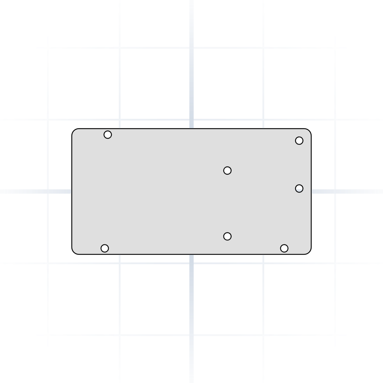
M3 holes on the Arduino Mega footprint. Carries RAMPS 1.4 control boards used in older printer builds.
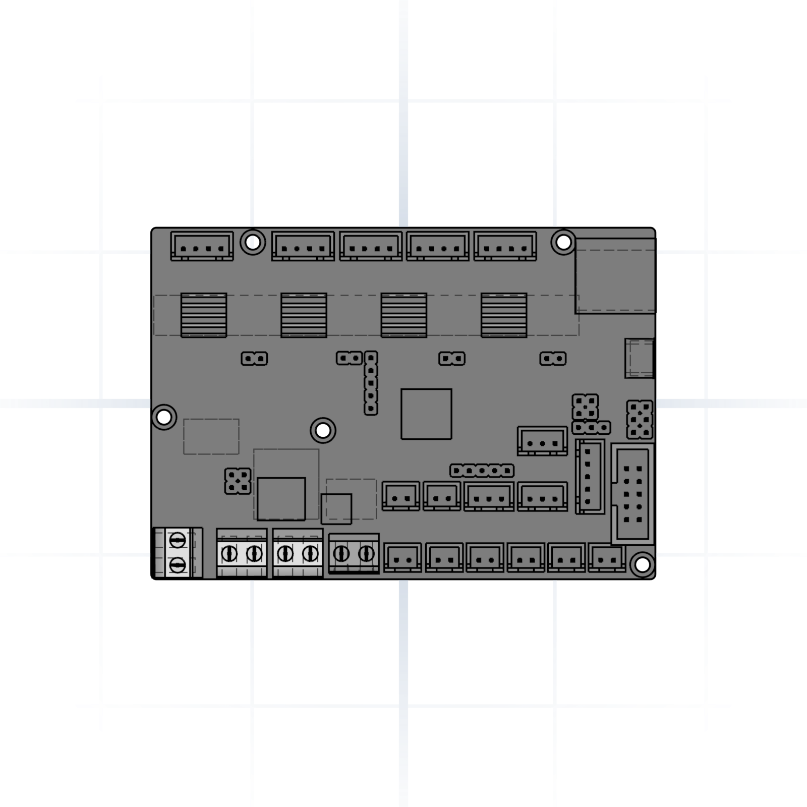
M3 hole patterns for BTT SKR Mini E3 or MKS Gen-L. Say which board and version you have; the mounting holes moved between versions.
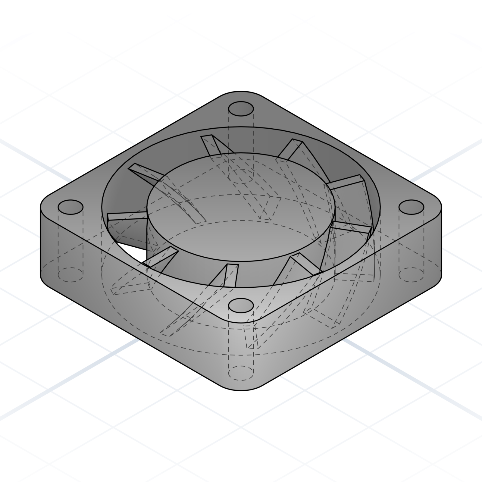
40 × 40 × 10 mm. M3 holes on a 32 mm square pattern. The hot-end cooling default.
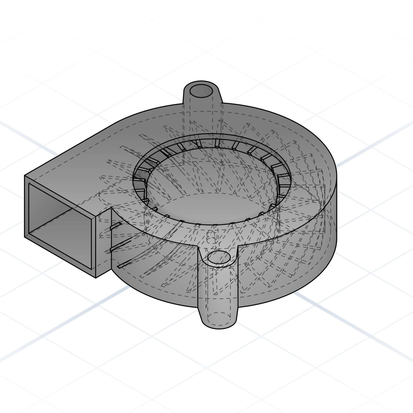
50 × 50 × 15 mm centrifugal fan. Two M3 mounts and a rectangular outlet. The part-cooling default.
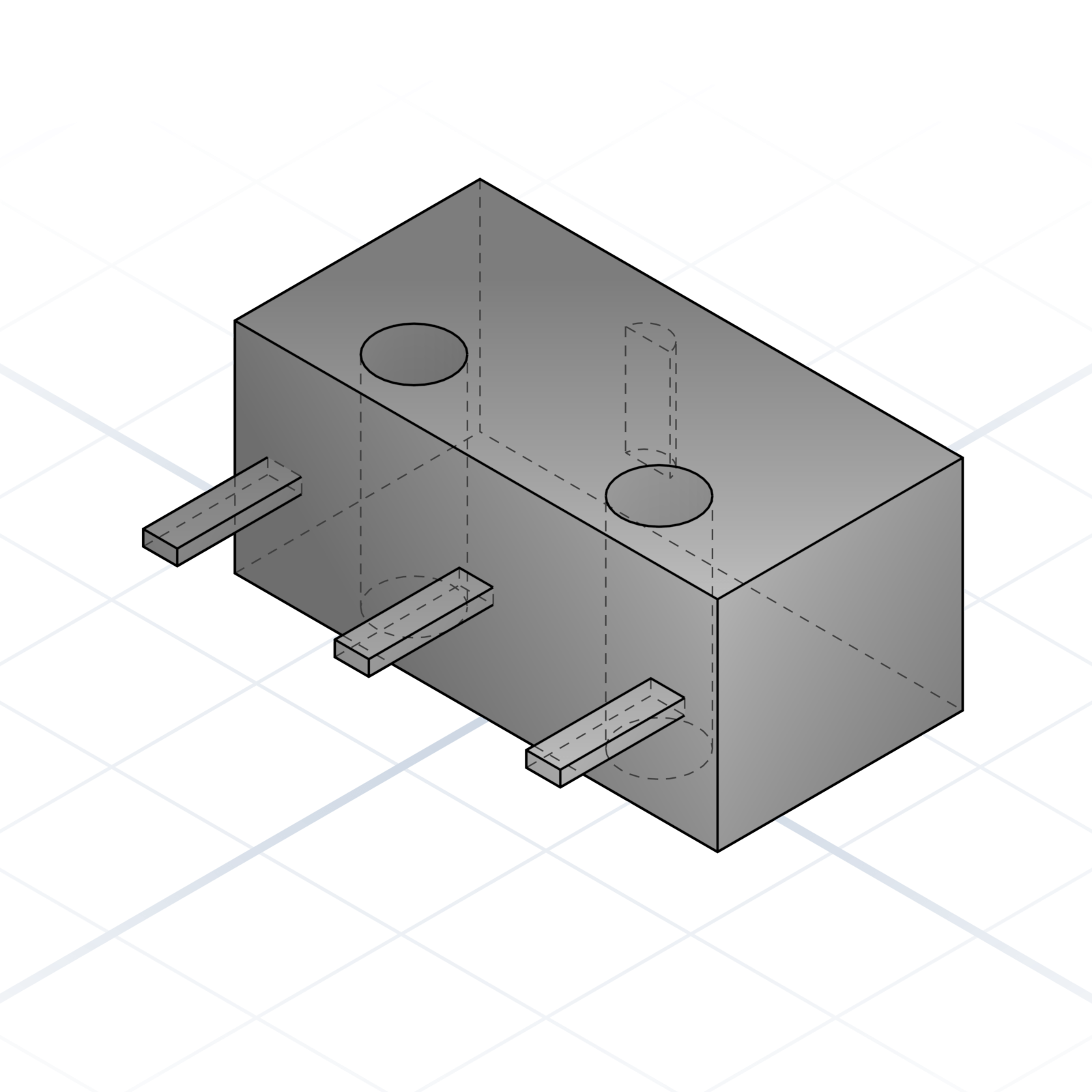
Omron D2F endstop. 5.8 × 12.8 mm body, two M2 holes 6.5 mm apart. Used for X / Y / Z homing.
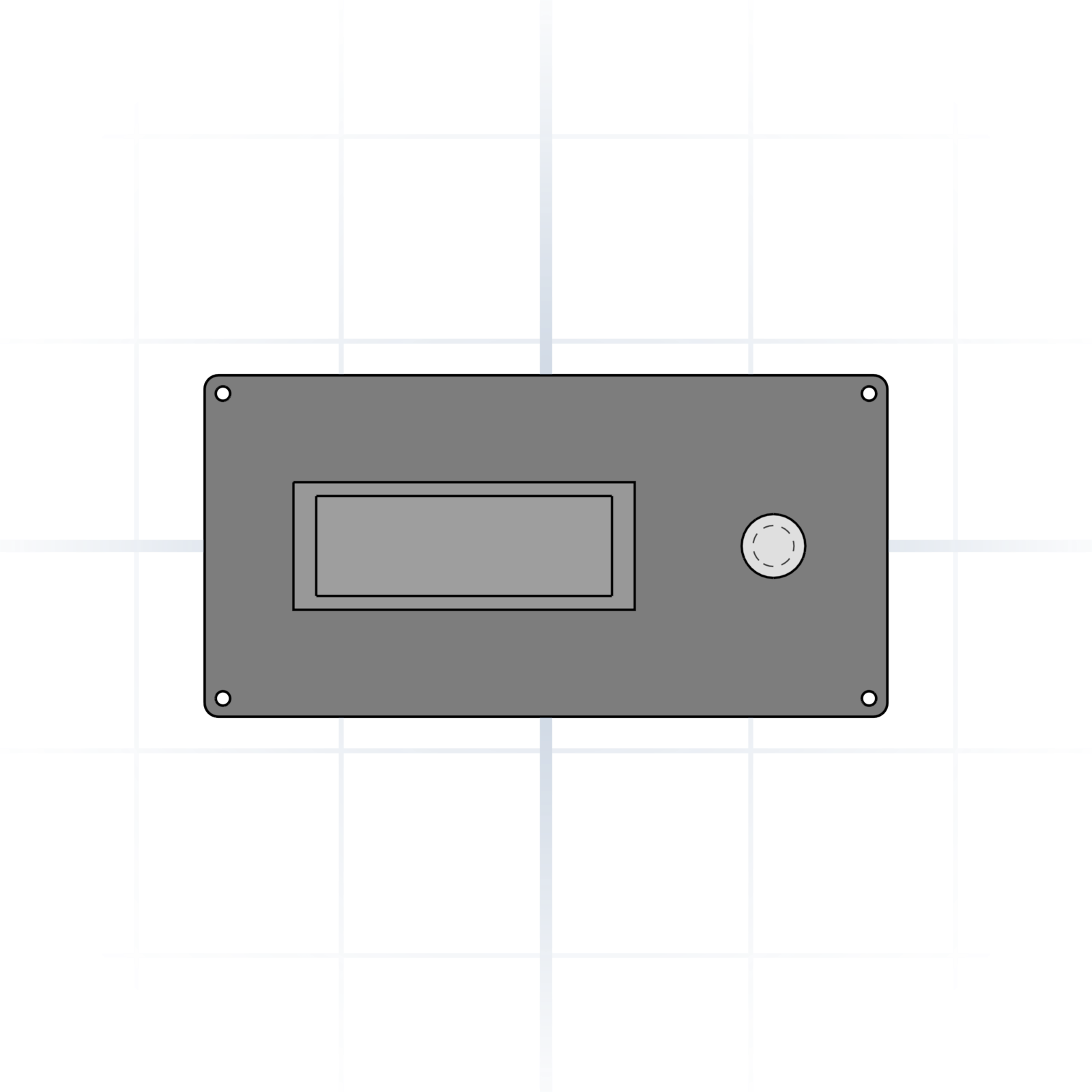
128 × 64 printer display with rotary encoder. Standard panel cut-out is roughly 150 × 75 mm.
The most popular way to organise a drawer or workbench. Snap-in bins sit on a gridded baseplate in fixed 42 mm squares, so everything lines up and stays put. Thousands of ready-made bins already exist online; ask for the size you need.
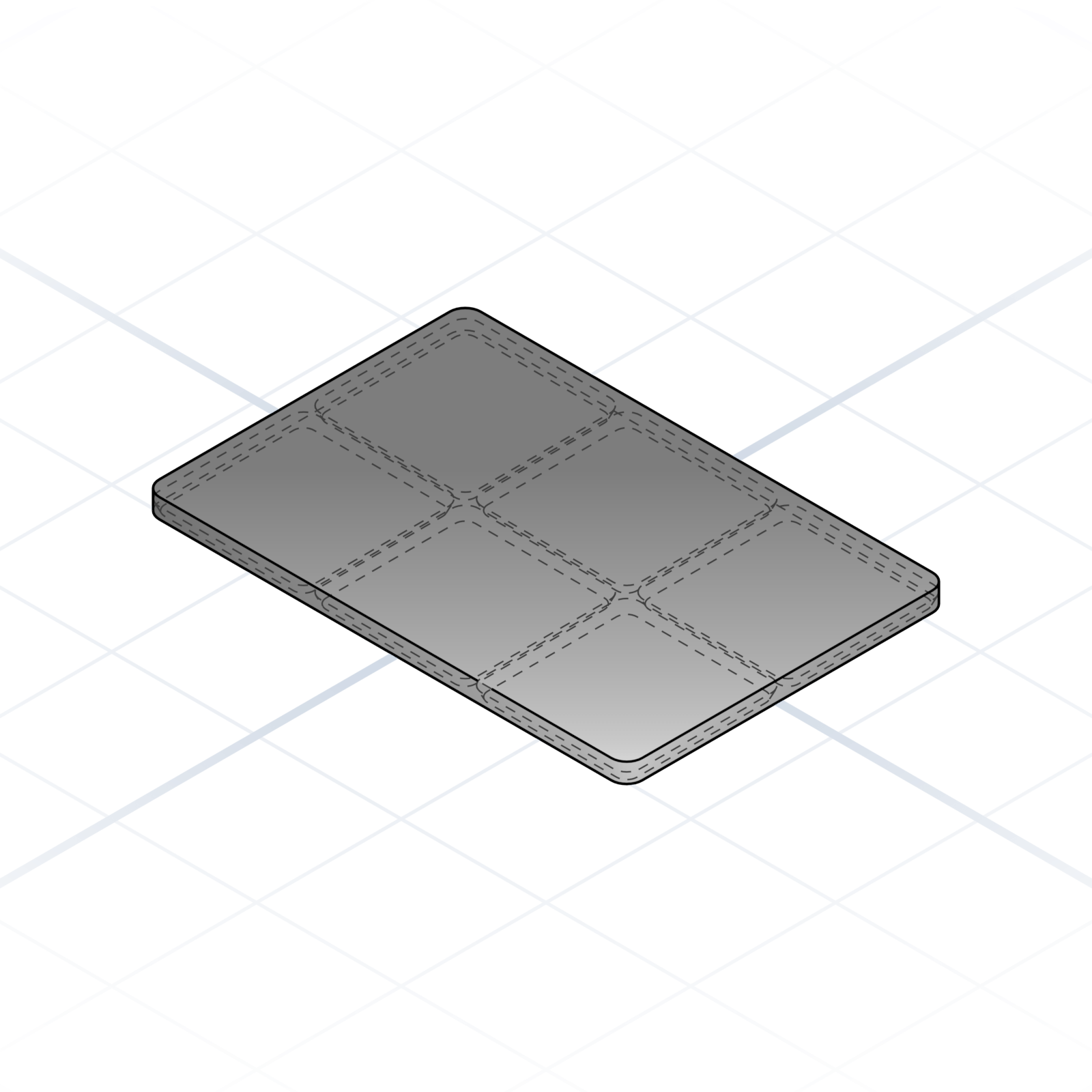
Tray with 42 mm pitch recesses that grip the chamfered foot of every bin. Bolt it to a drawer bottom and every bin has a home.
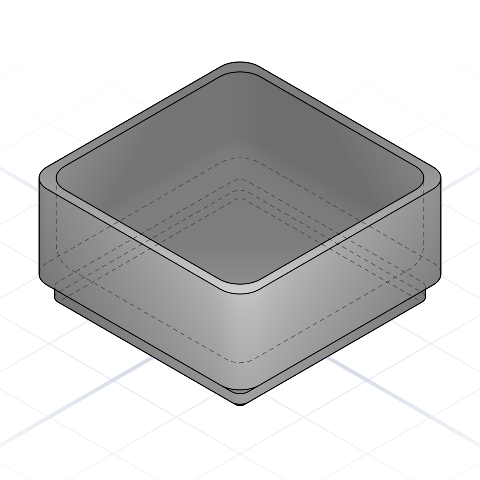
The 42 × 42 × 21 mm base unit, one square on the grid. Ask for it hollow, or split into compartments inside.
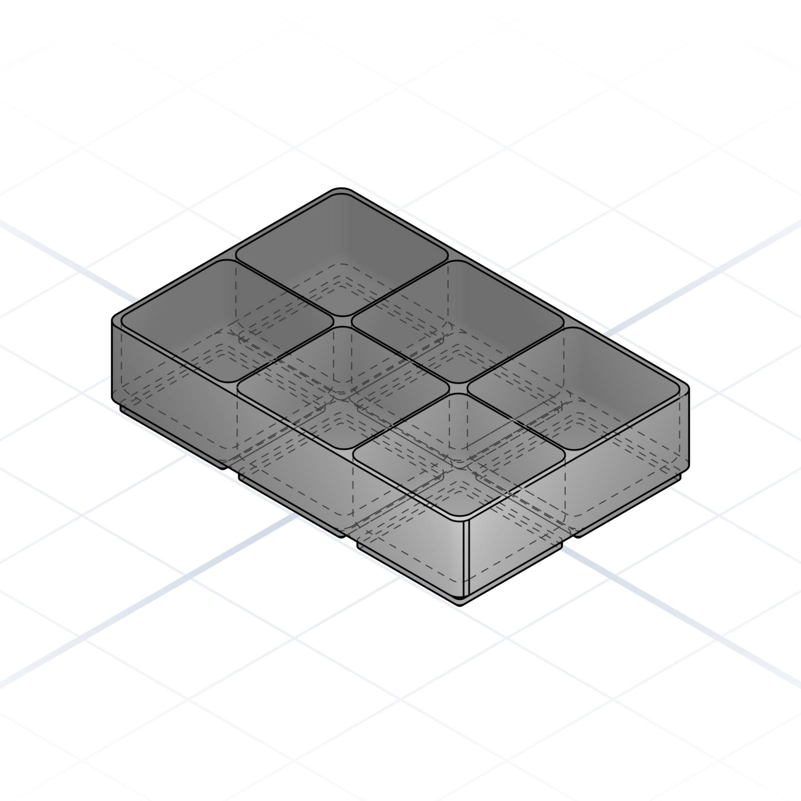
Any rectangular footprint works: 2 × 3, 4 × 1, 5 × 5. Tell the AI how many squares wide and deep, plus the height; the baseplate stays the same.
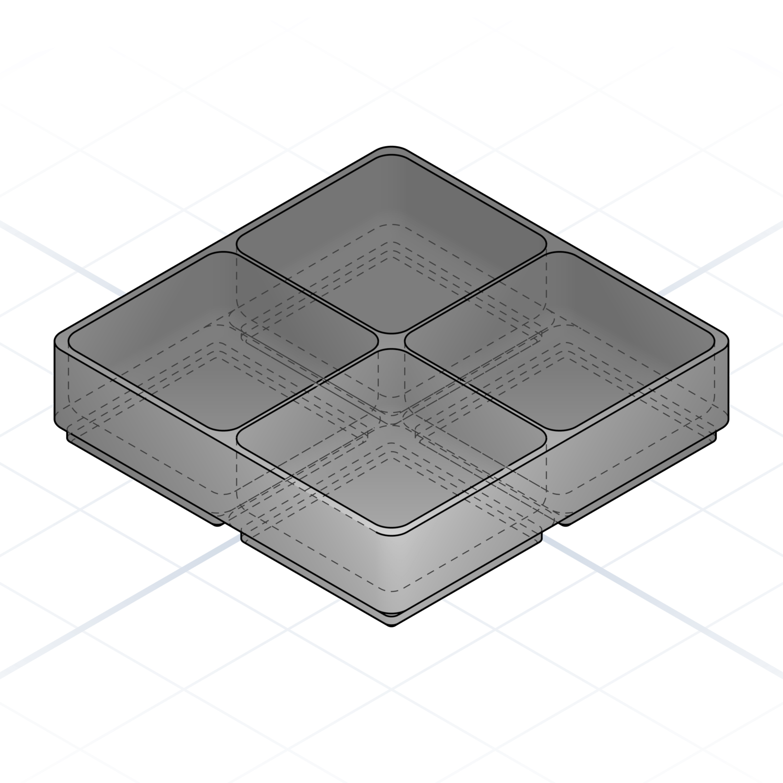
Split the inside into a grid of compartments. Four cells in a 2 × 2 bin sorts a kit of screws and washers.
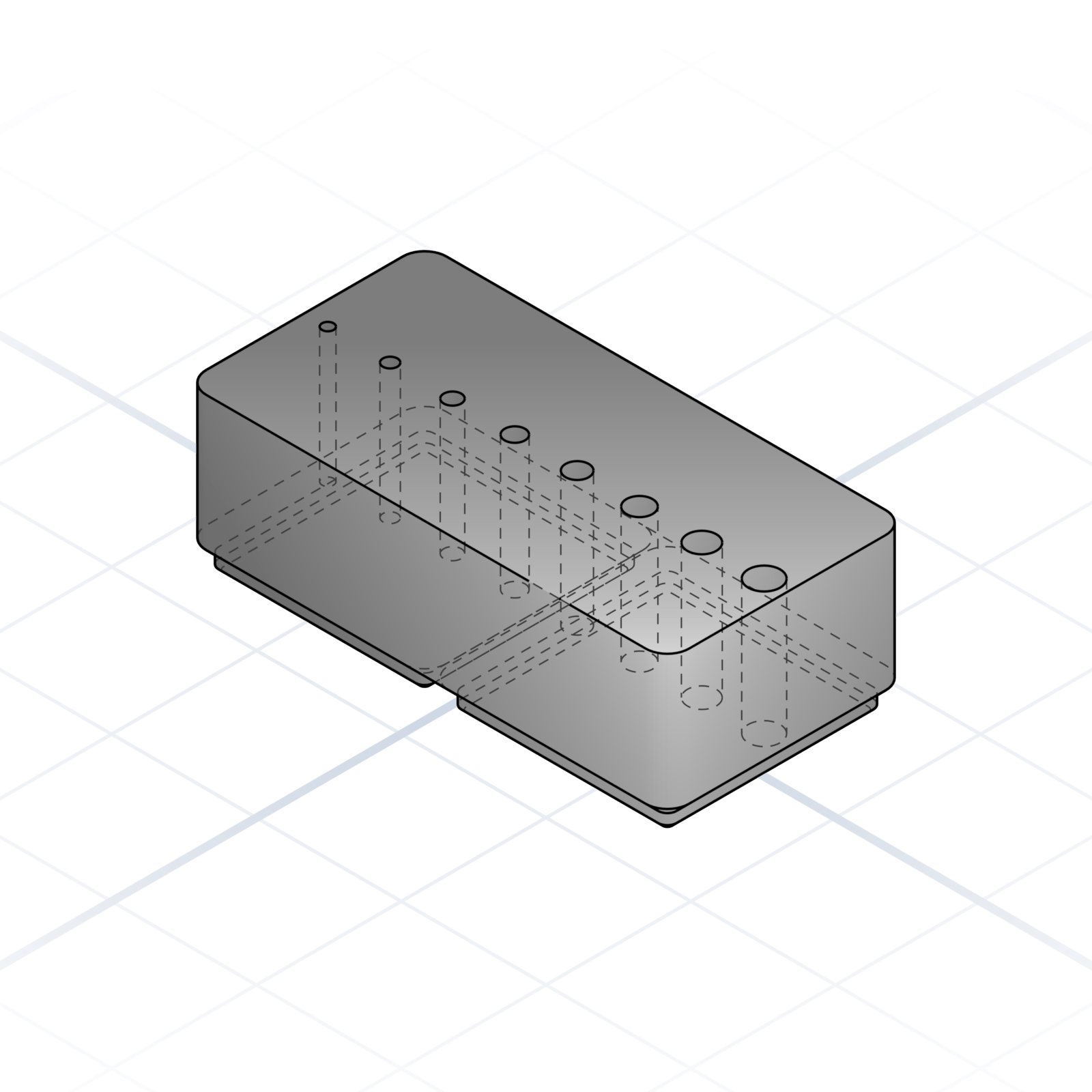
A row of holes in graduated sizes, one per drill bit, each with room for a printed label. Every bit gets a home instead of rattling in a box.
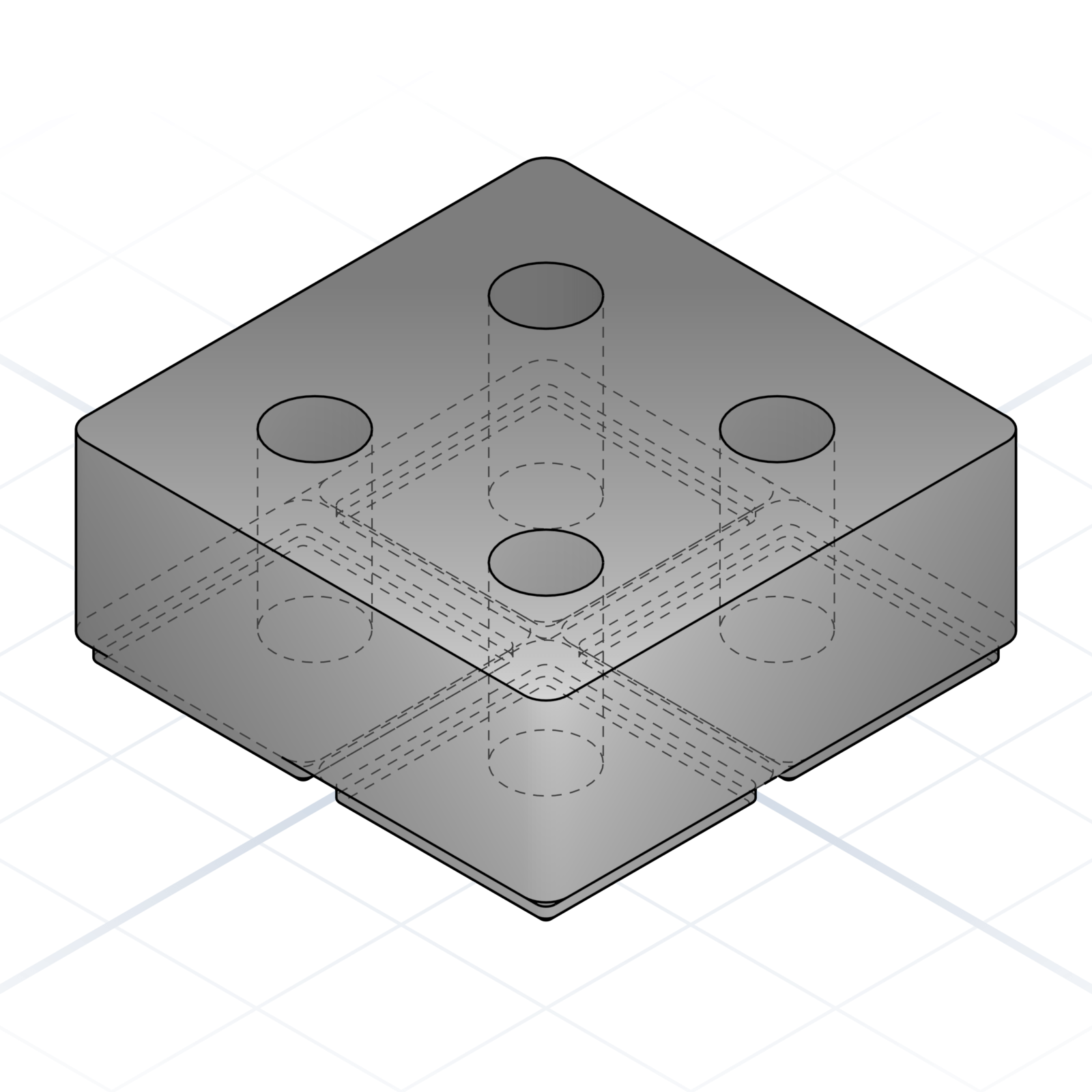
Bin with circular pockets sized for the tool shanks. Screwdriver bits, end mills, calipers: each one has a slot and won’t roll around.
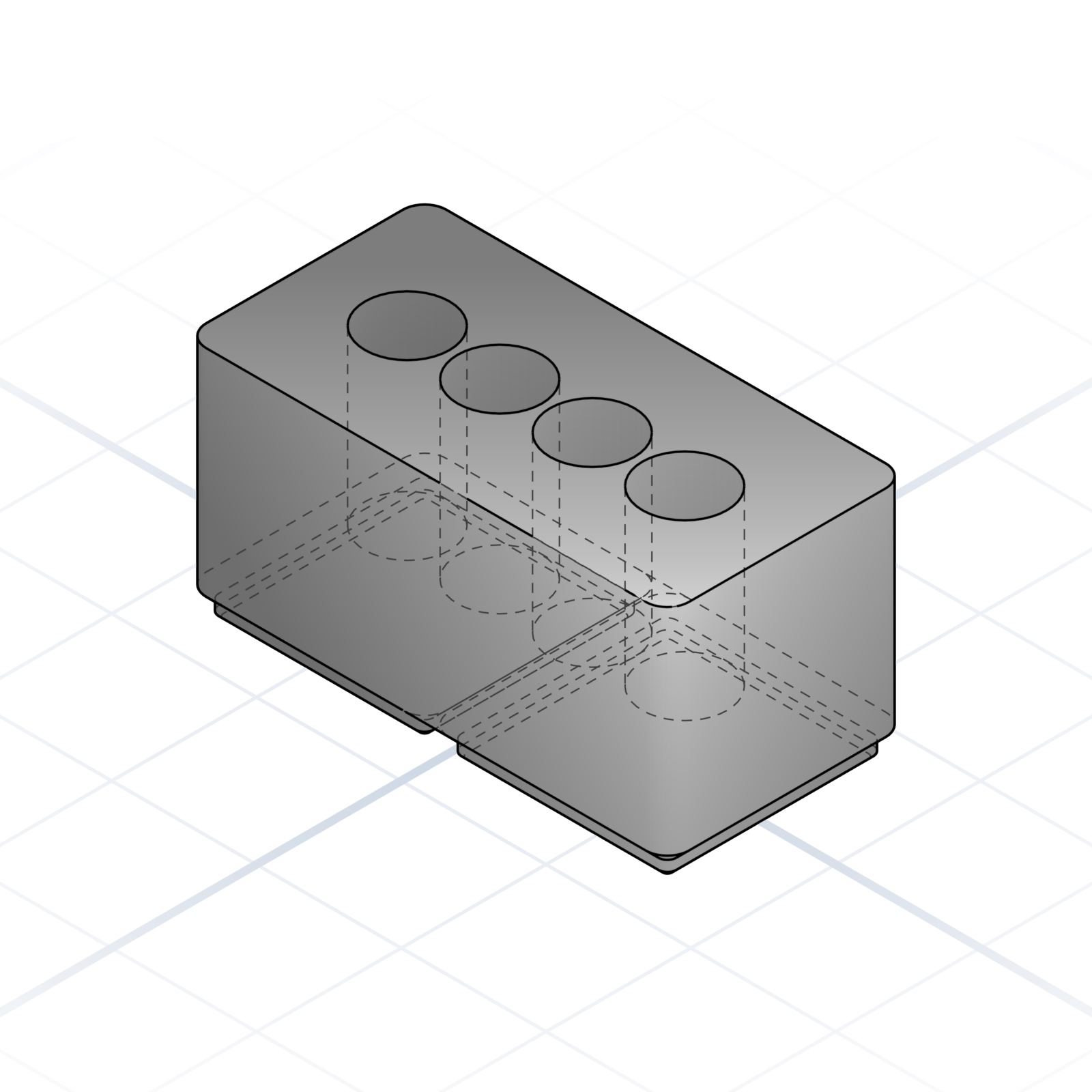
Tall bin with deep round holes. Markers, AA batteries, 18650 cells, paint pens stand on end and never roll off the bench.
Pick sizes that the printed plastic can actually hold. These are the defaults seasoned makers reach for.
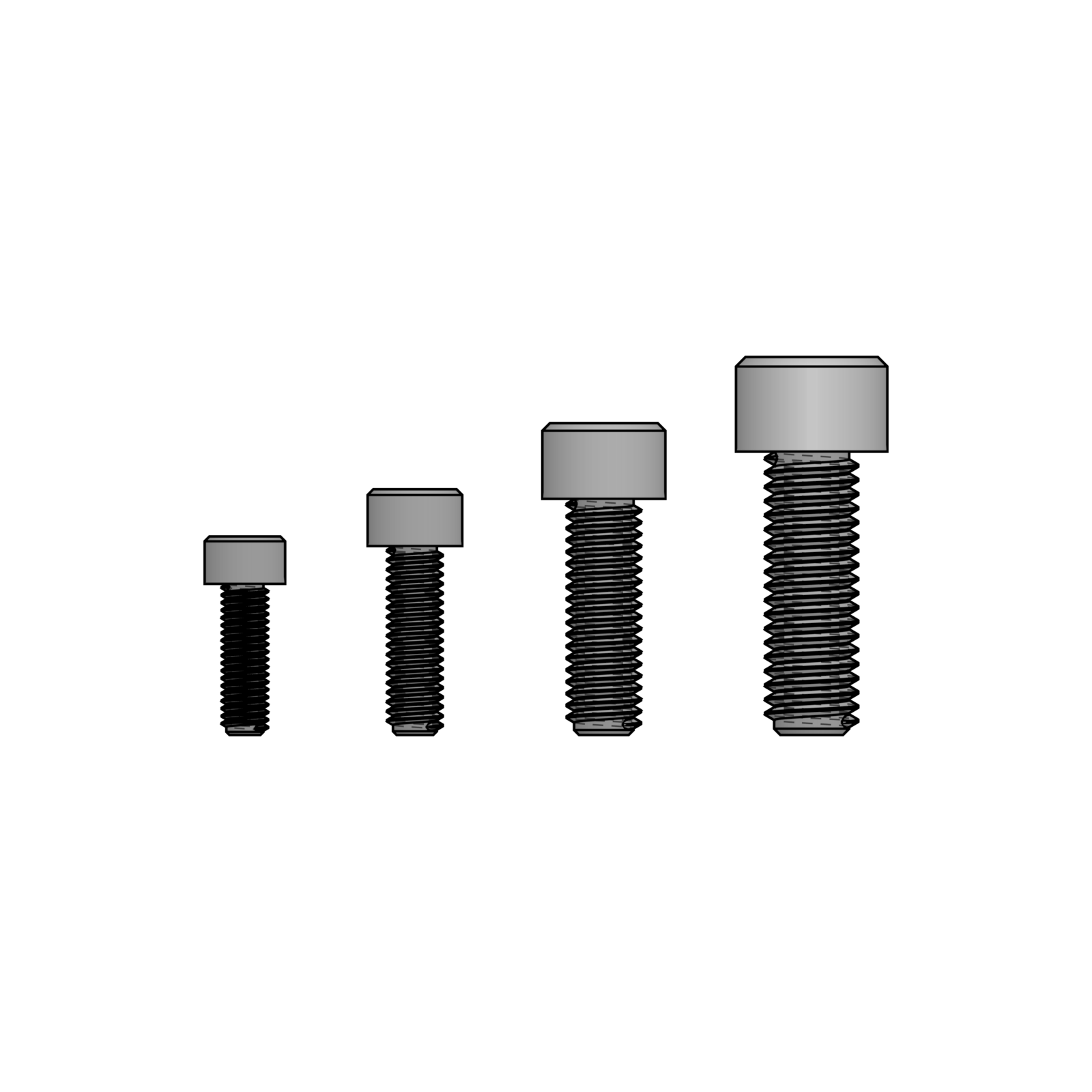
M5 is the smallest size that grips printed plastic reliably. M6 for everyday brackets, M8 / M10 for load-bearing joints. M3 strips out at the first over-tighten, so skip it unless you’re using a heat-set insert.
Brass insert melts into a printed boss and provides the threads. Design the boss at 8.5 mm OD for M5, 10 mm for M6. Thinner walls split when the insert melts in.
LM8UU bearings, 8 mm chromed rod. The whole ecosystem assumes this size: couplers, brackets, leadscrews all line up.
Cheap, plentiful, presses into a 22 mm pocket: model it at 22 mm (±0.1 mm) or add crush ribs. 624 / 625 work too; below 4 mm bore is fragile.
4 mm knuckle around a 1.75 mm pin (a filament offcut or steel rod). A common, well-tested size. Smaller knuckles split; bigger waste plastic.
20 × 20 mm aluminium extrusion with a 6 mm T-slot. M5 T-nuts drop straight in. 3030 if you need more rigidity.
2 mm pitch, 6 mm wide. 16T or 20T pulleys on a 5 mm shaft. Everything heavier than a print head wants 9 mm width.
7 mm head, 11 mm long total. The push-and-click connector between two printed parts. Replaces a screw on light-duty joints. Below a 5 mm head the petals get fragile; above 10 mm it’s a screw waiting to happen.
The two kinds of model you can ask for, pictures as input, colour and texture, and parts that adjust themselves with a slider.
Two kinds of geometry. A parametric part is built from dimensions and stays editable; an organic model is a sculpted mesh. What you ask for decides which.
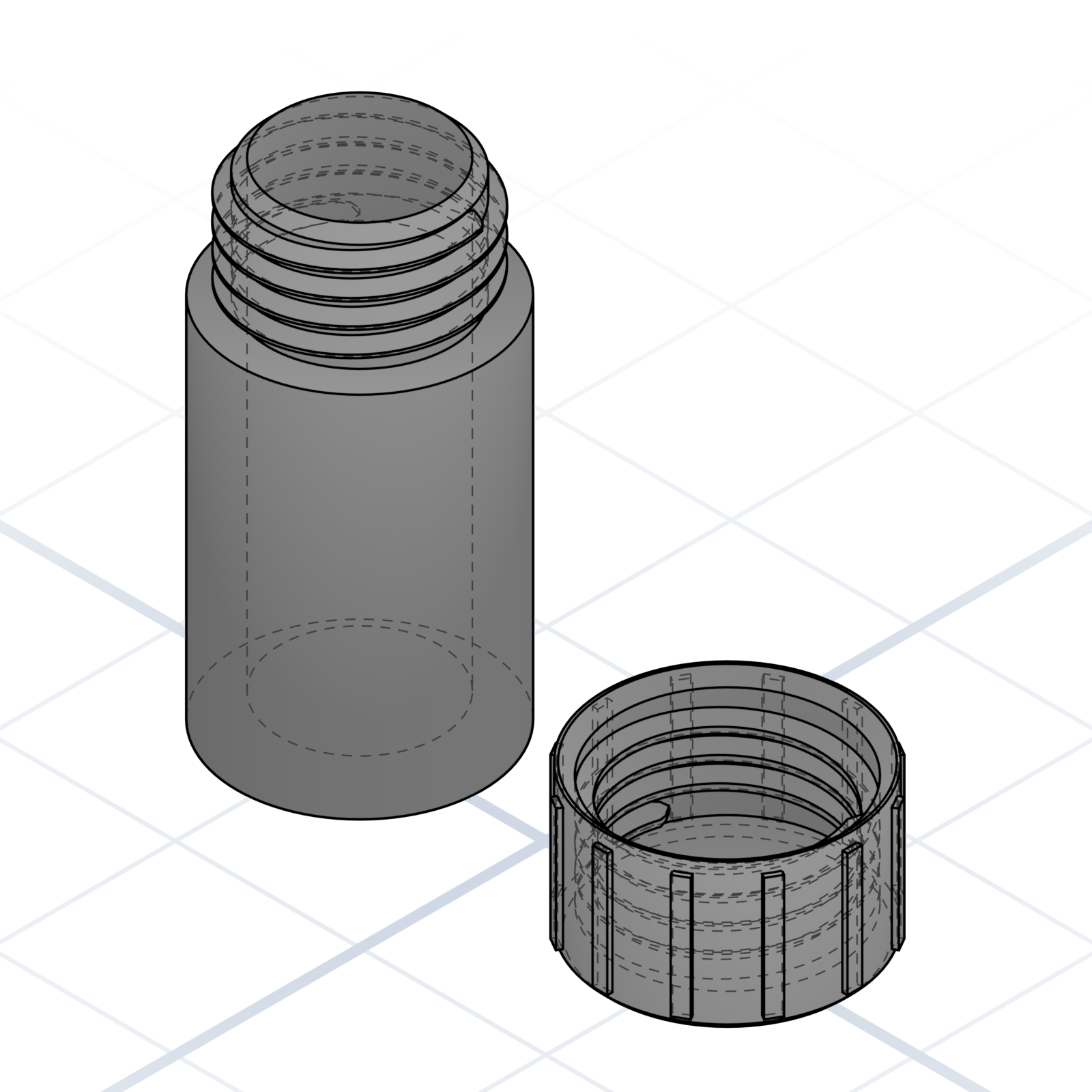
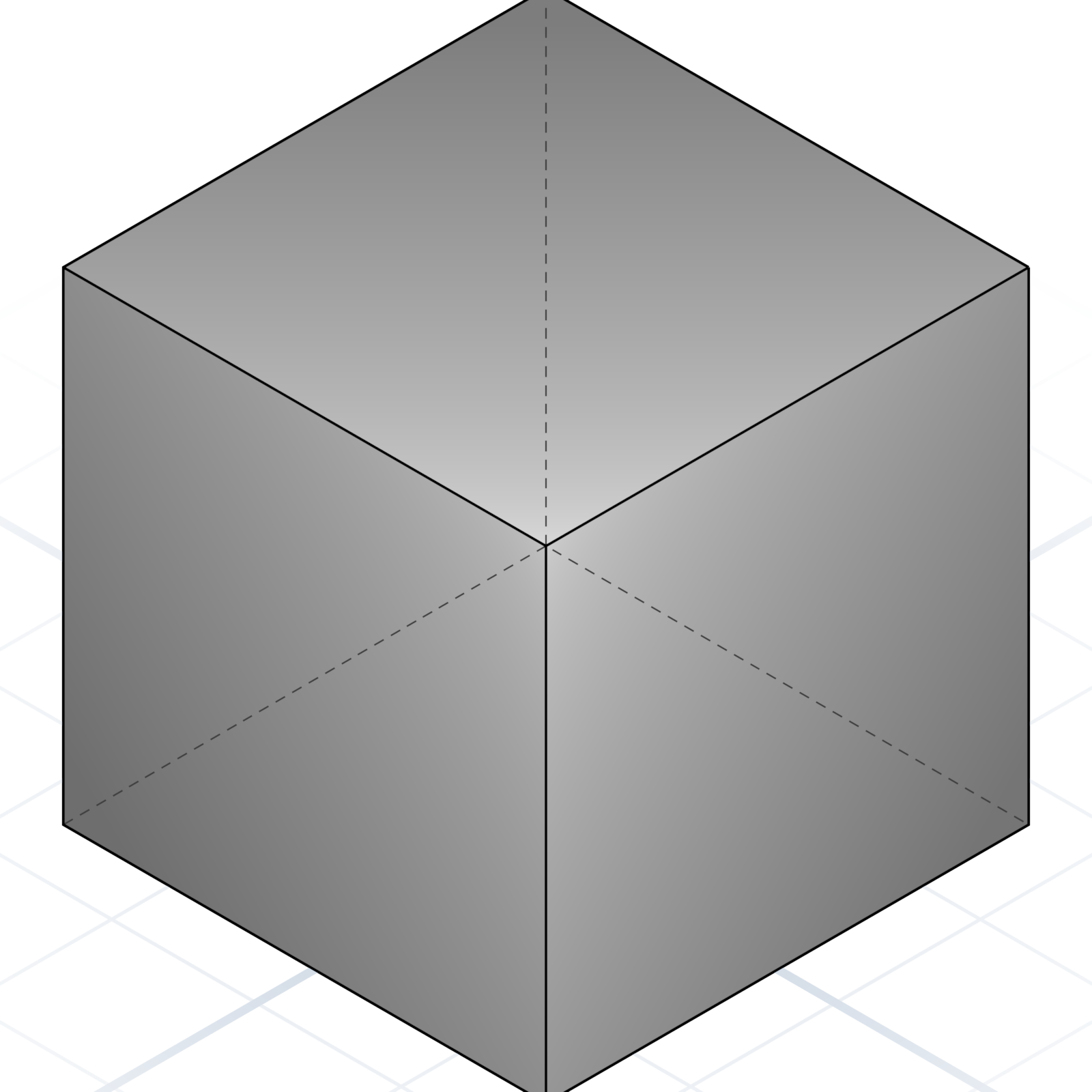
“A 40 mm tall container with a threaded lid.” Dimensions and booleans, exact to the millimetre and still editable. The default unless you ask for something sculpted.
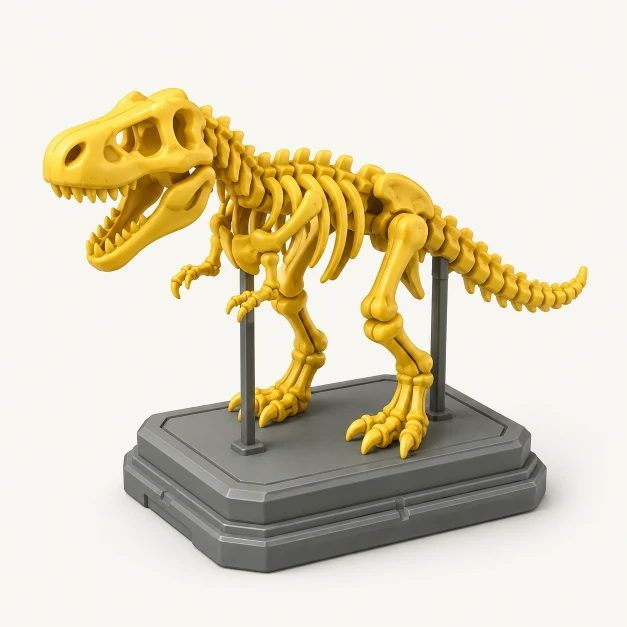
“A dog head.” “A small dragon.” Name a creature or a character and you get a sculpted mesh instead. No primitives, no dimensions to type.
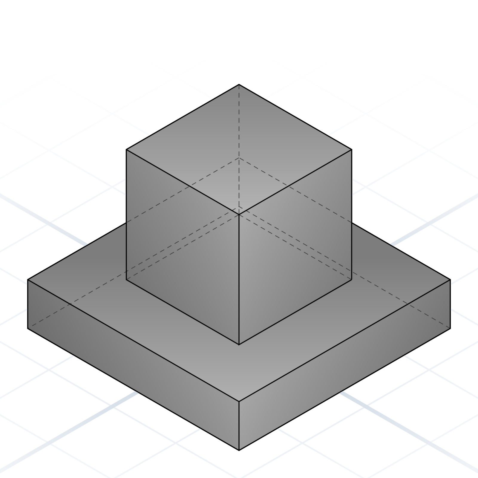
“A wine stopper with a dog head on top.” Each half gets built separately, then the two are merged. The parametric half keeps its sliders.
You can’t put sliders on a sculpted shape, only on parametric parts. Change an organic shape by asking again, a parametric one by tuning it in place. Parameters live on page 30.
Hand over a picture instead of a paragraph. A dimensioned sketch becomes a parametric part; a photo of a subject becomes an organic model.
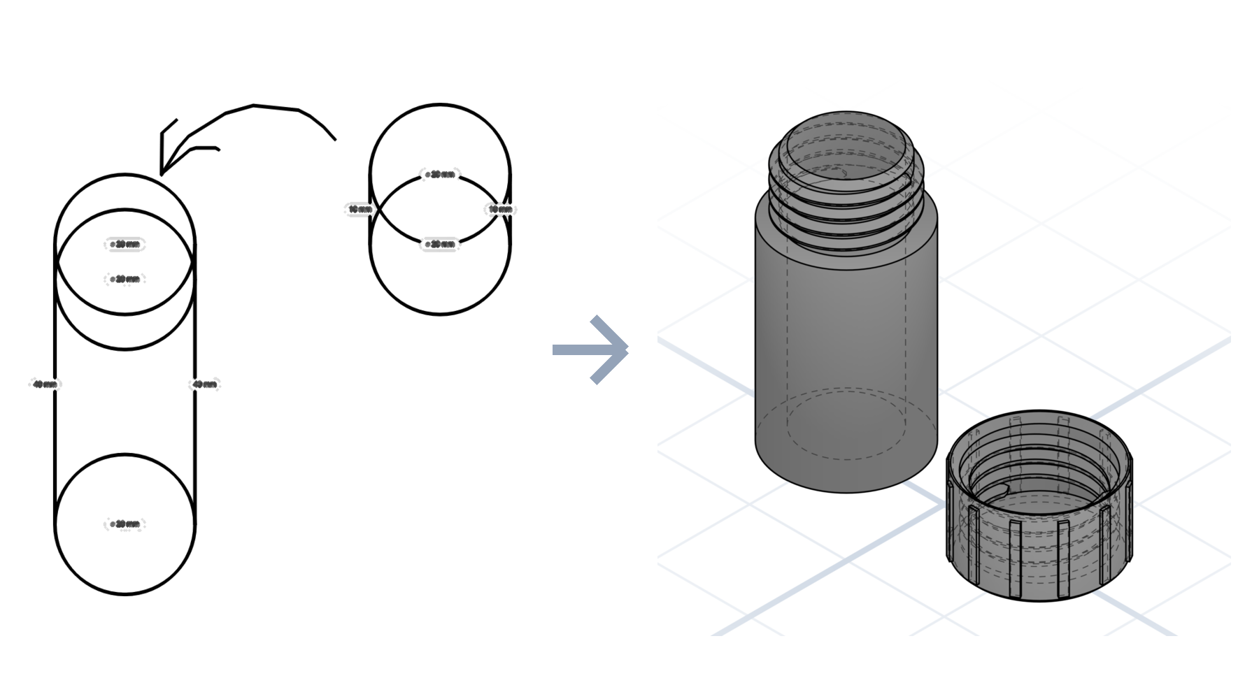
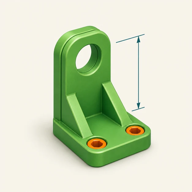
Upload the drawing, and spell out everything you know in words too: dimensions, parts, tolerances. Those become real parameters, still adjustable. Whatever you leave off, it has to guess.
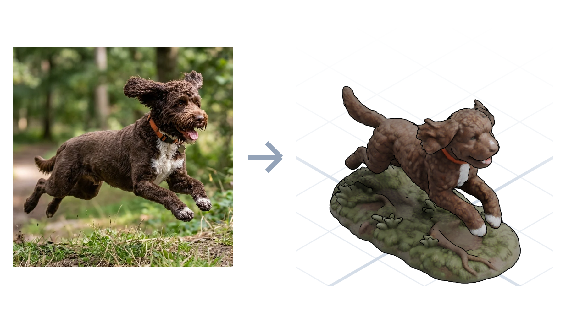
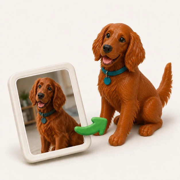
Upload a photo of your dog or a figurine, and still say exactly what you want. A photo alone leaves too much open. The mesh reads shape, not scale, so give the size too.
Surface texture is organic only. Colour works on both: a sculpted mesh takes textures or colour segments, a parametric part takes one tag per part.
“A dragon with scales.” “An elder tree with bark.” The surface detail is baked into the mesh. Comes out as a coloured 3D file, ready to view or display.
“Colour the dragon’s wings red, body green and yellow.” Sculpted and imported meshes only. Comes out as a separate piece per colour, ready for a printer that changes colours automatically.

No surface texture, but every part carries its own colour tag. Handy for reading an assembly at a glance, and slicers put each colour on its own filament.
Parameters make a finished model adjustable: nudge a size or toggle a feature in place, with no full regeneration, so changes are faster and cheaper. Ask for the ones you want and GrandpaCAD proposes the rest. Worth adding whenever you’ll remake a part at new sizes.
“Make the wall thickness a slider from 1 to 5 mm, starting at 2.” Use for any number with a range.
“Let me type the name for the engraving.” A single line of text: keychains, signs, name tags.
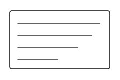
“Let me write a few lines on the back.” A bigger box for several lines: dedications, addresses, longer labels.
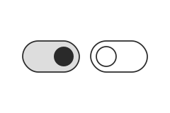
“Add a switch that turns the colours on.” Flip the colours, a lid, or a hole pattern on and off. No regeneration needed.
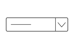
“Make the text style a dropdown: raised, engraved, or cut through.” Use when the answer is one of a fixed set.
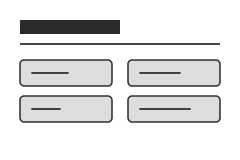
“Put size settings under a Dimensions group and decoration under Style.” Keeps long parameter lists tidy.
Words became a model; now the model becomes plastic. Filament, export, slicing, and the machine doing the melting.
Each filament has its strength. Start with PLA, then choose by what the part must handle.
These are the staples. There are loads more (silk, matte, wood-fill, glow-in-the-dark, even metal-filled), but you rarely need them.
Azurefilm, a Slovenian shop. Not a sponsor, just one we like.
The model has to leave the screen. A few habits keep parts printable on the first try.
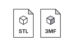
3MF preserves units and colour. STL is the lowest common denominator every slicer accepts.
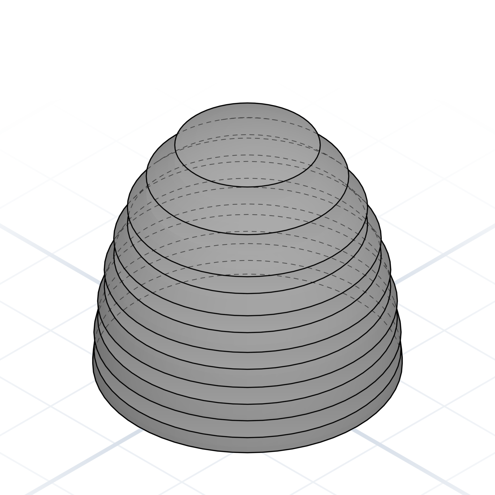
The exported file opens in a slicer such as PrusaSlicer, Cura, or Bambu Studio. It cuts the model into layers and sends them to the printer. The next pages explain its words.
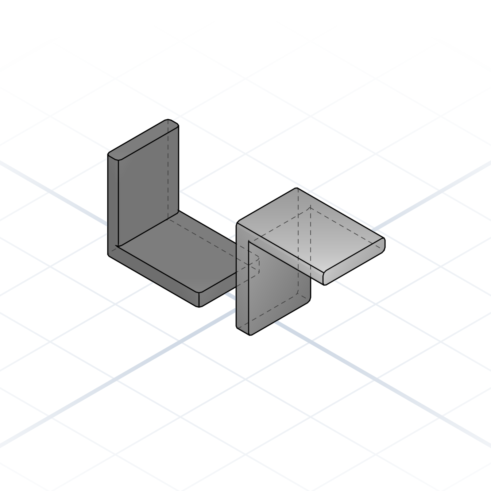
Flat side down by default. Threads, holes, and engraved text want to face up.

Chamfer overhangs to 45° and most prints don’t need supports at all.
The words the slicer uses. Knowing them lets you describe a part with the print step already in mind.
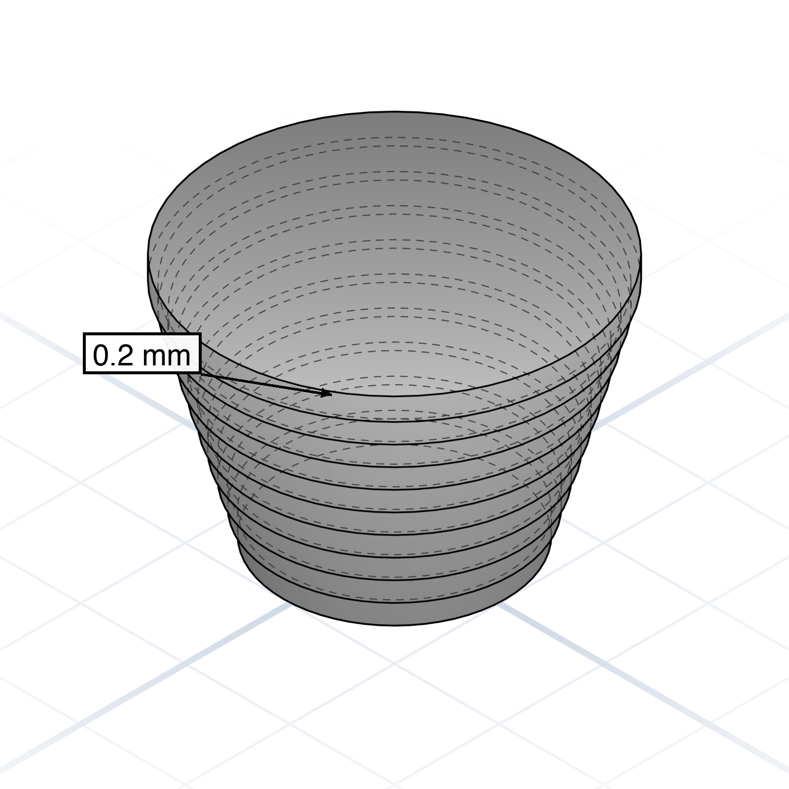
Thickness of each printed slice. 0.2 mm is the everyday default; 0.12 mm for detail, 0.28 mm for speed.
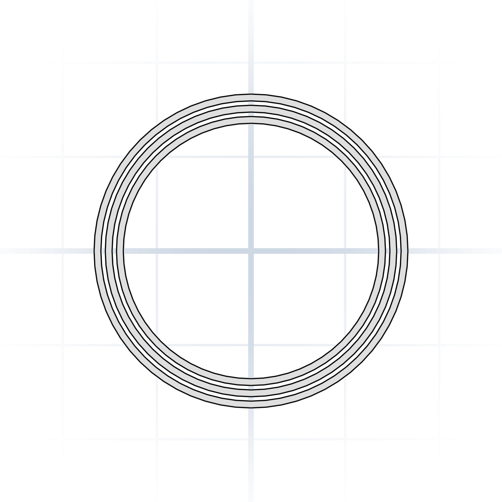
The shell loops around each layer. Three walls (~1.2 mm) is the strength default.
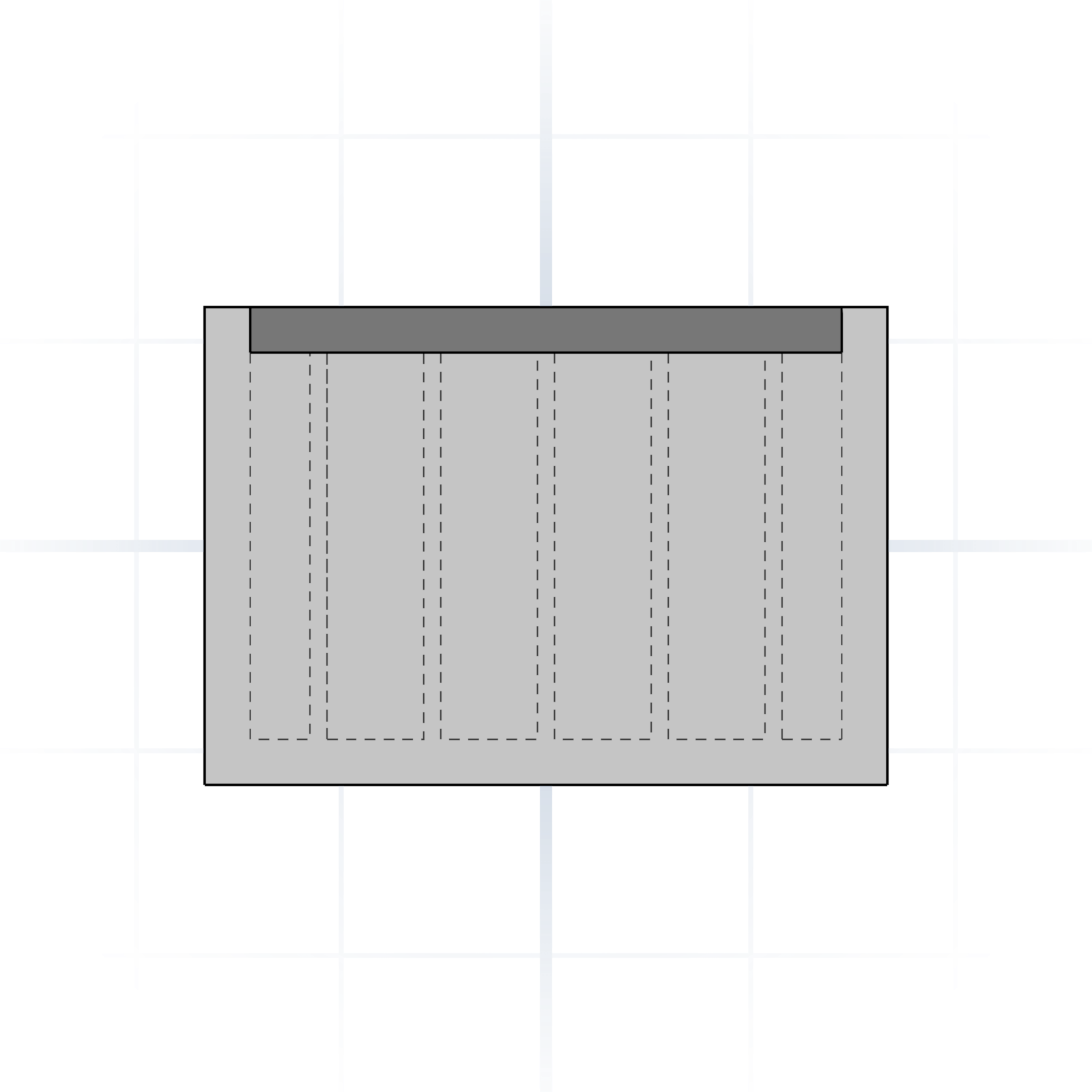
The honeycomb-like fill inside. 20% is fine for most parts; 80%+ for parts that carry weight.
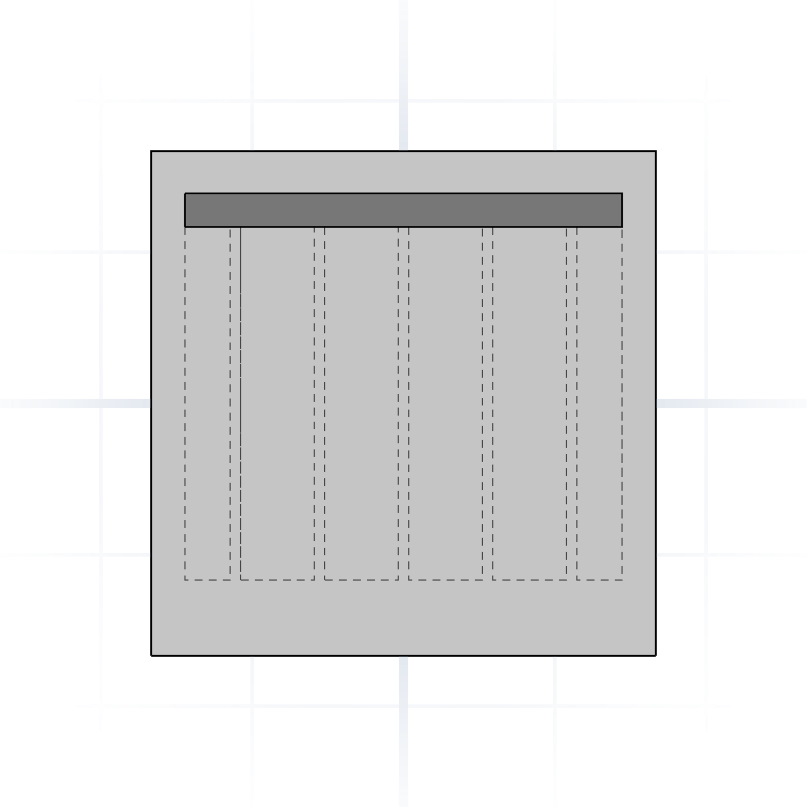
Solid layers that close the part. Four to five layers stops infill from showing through.
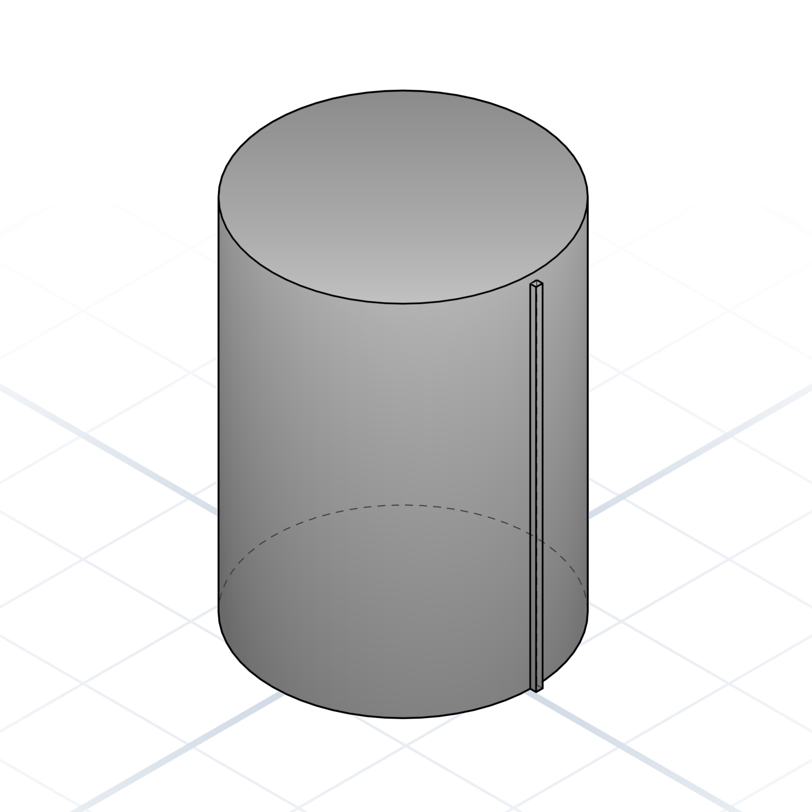
The vertical line where each layer starts and stops. Hide it on a back corner with “Aligned” or “Random”.
What the slicer adds around your part so tricky shapes survive printing, and what each helper costs.
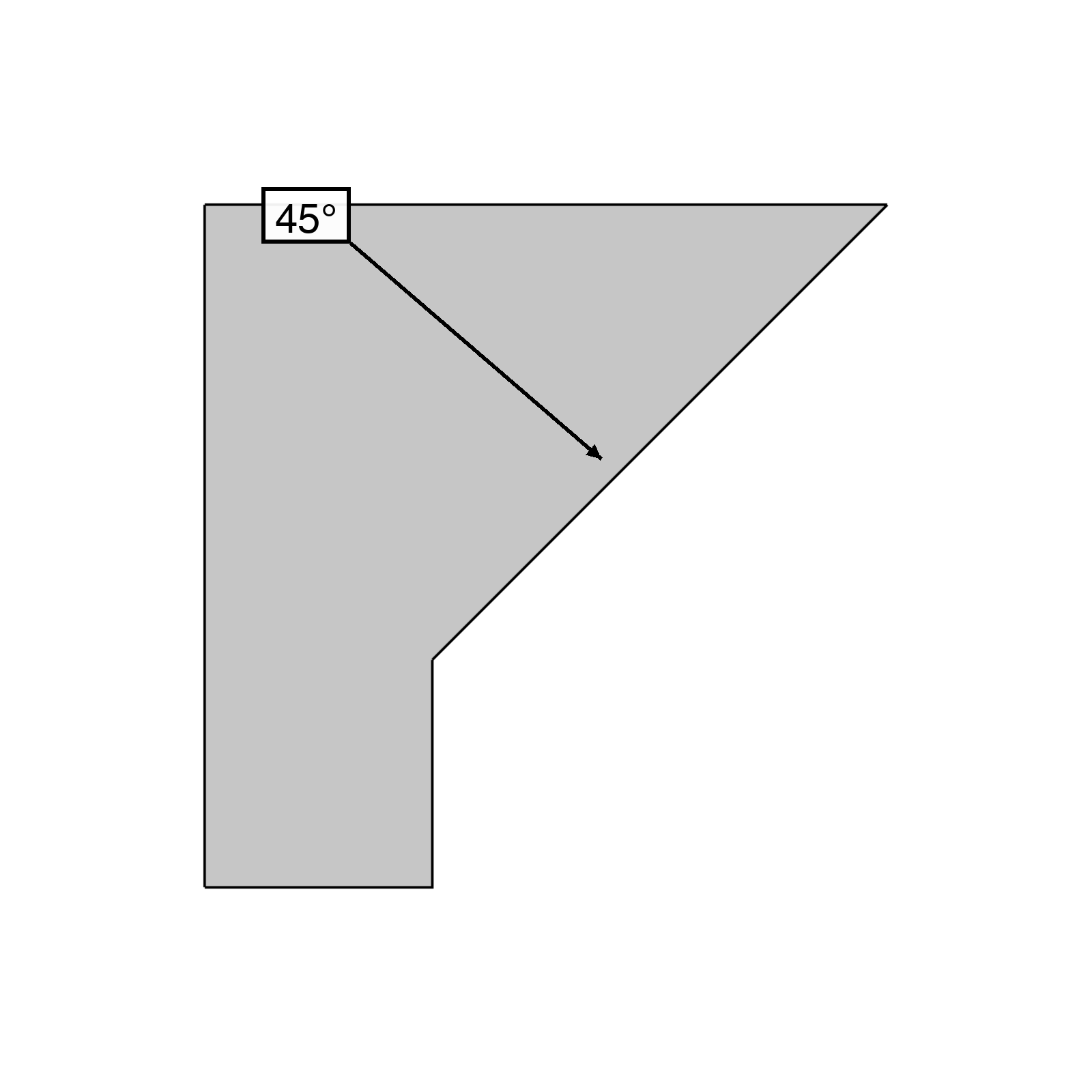
A face leaning out from vertical. Above 45° usually needs support; below prints free.

Flat span between two supports printed in mid-air. Up to ~10 mm prints cleanly.
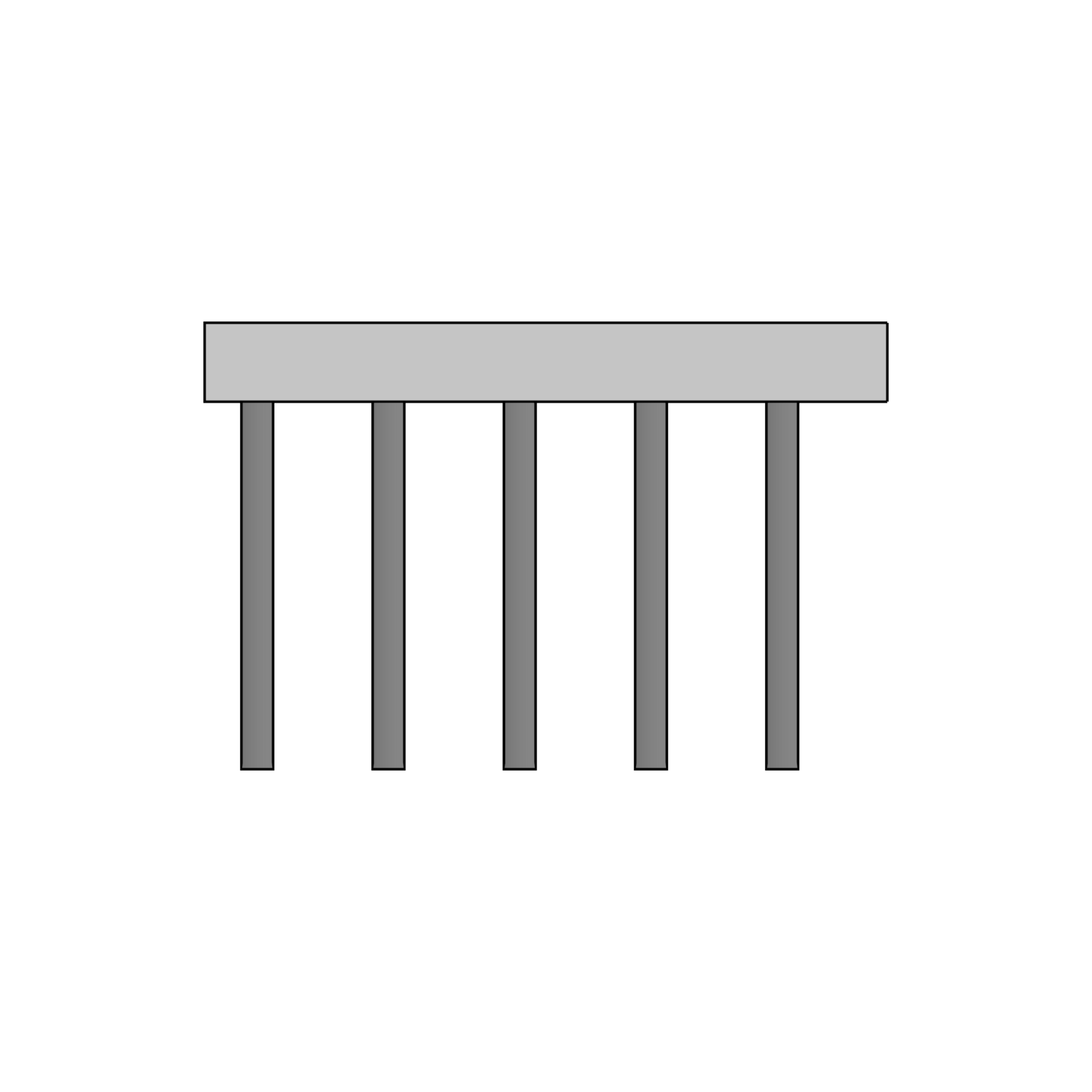
Scaffolding under overhangs, removed after printing. Tree supports use less material than grid.
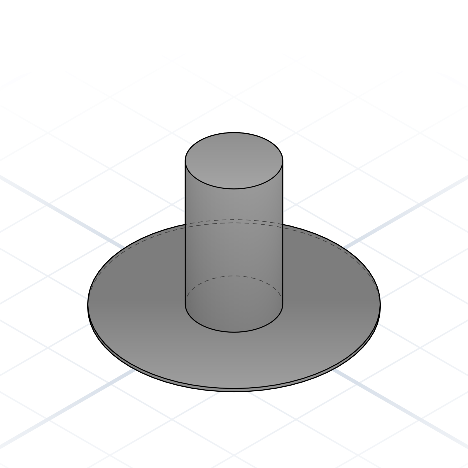
Single-layer skirt fused to the part. Adds bed adhesion for tall parts and narrow footprints.
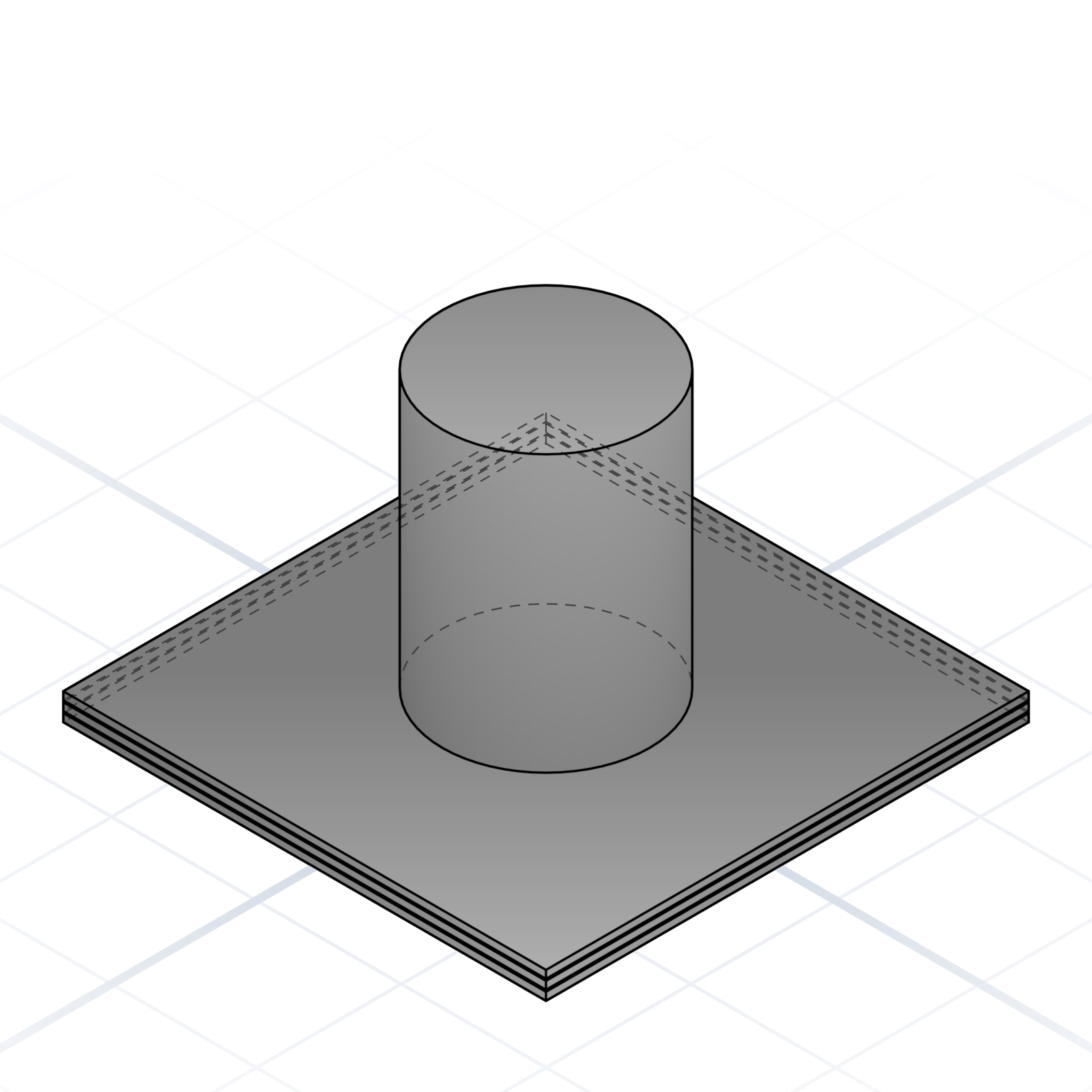
Sacrificial base layers under the part. Heavier than a brim; reach for it on warpy materials.
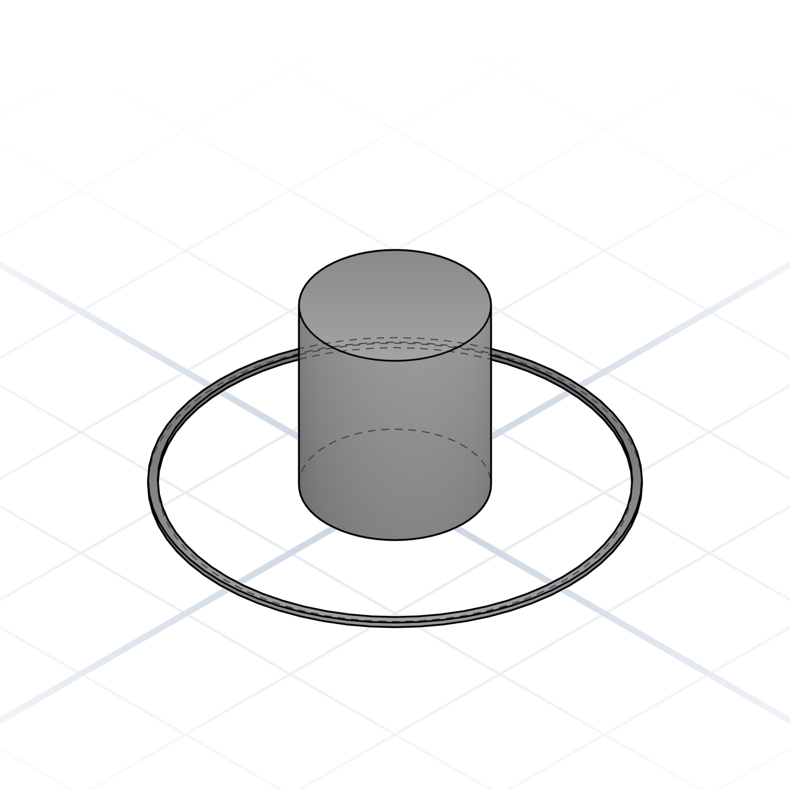
A loose loop around the part, not touching it. Primes the nozzle before the real print starts.
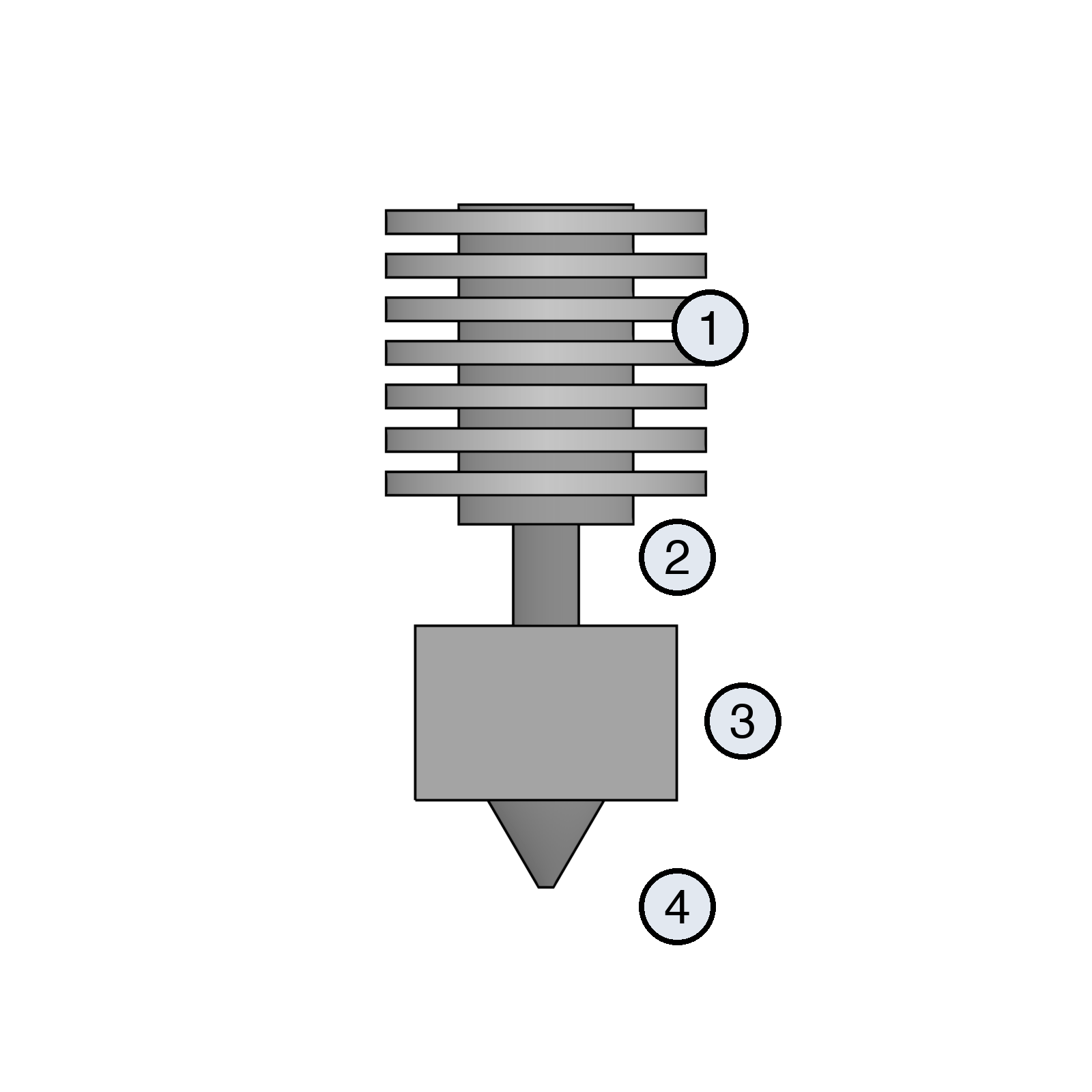
The parts that melt and push filament. Every printer has them; the names come up when you swap a nozzle, clear a clog, or design an accessory.
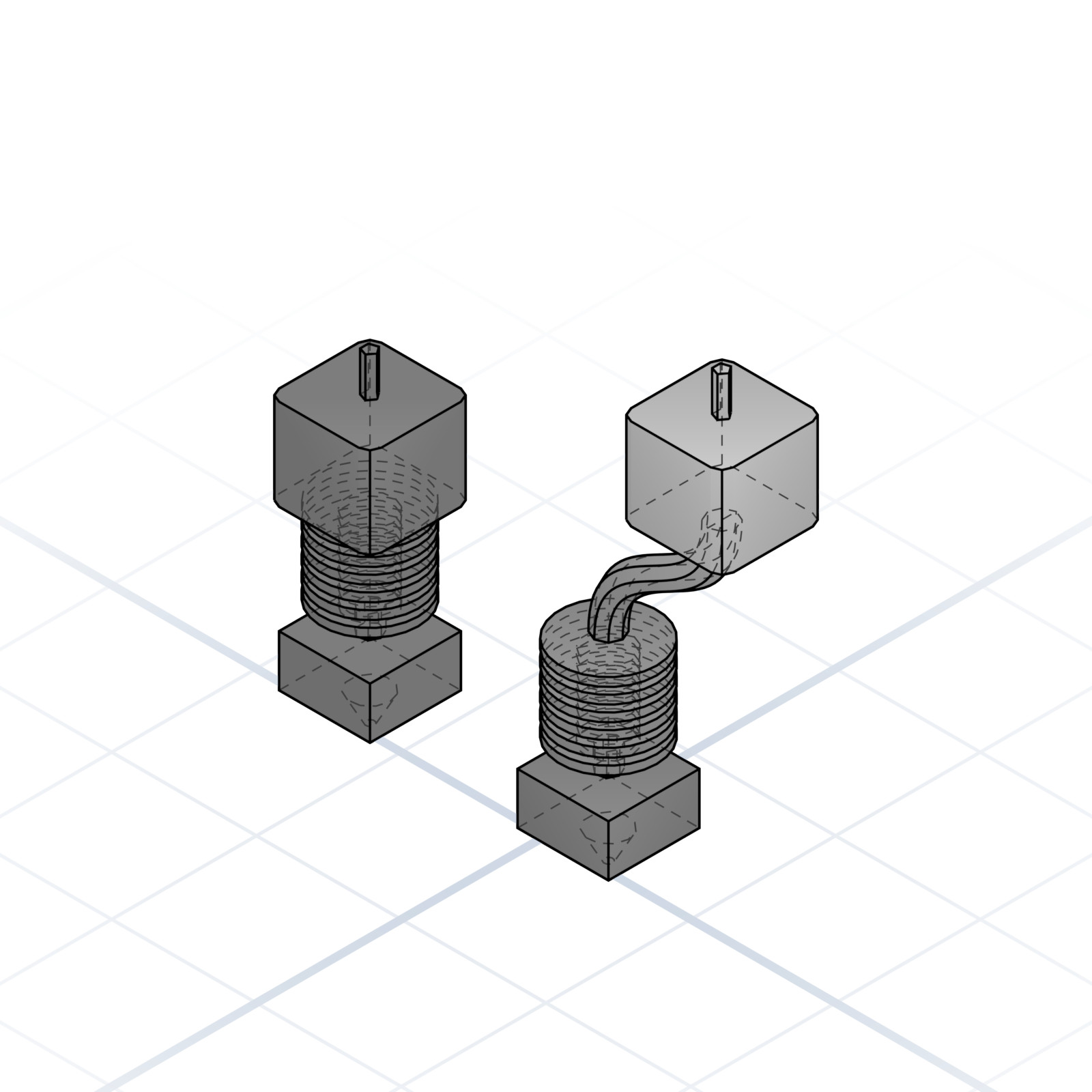
The extruder is the motor and gears that push filament. On the print head it is direct drive (most modern printers, including the Bambu Lab A1). On the frame, pushing through a long tube, it is Bowden.
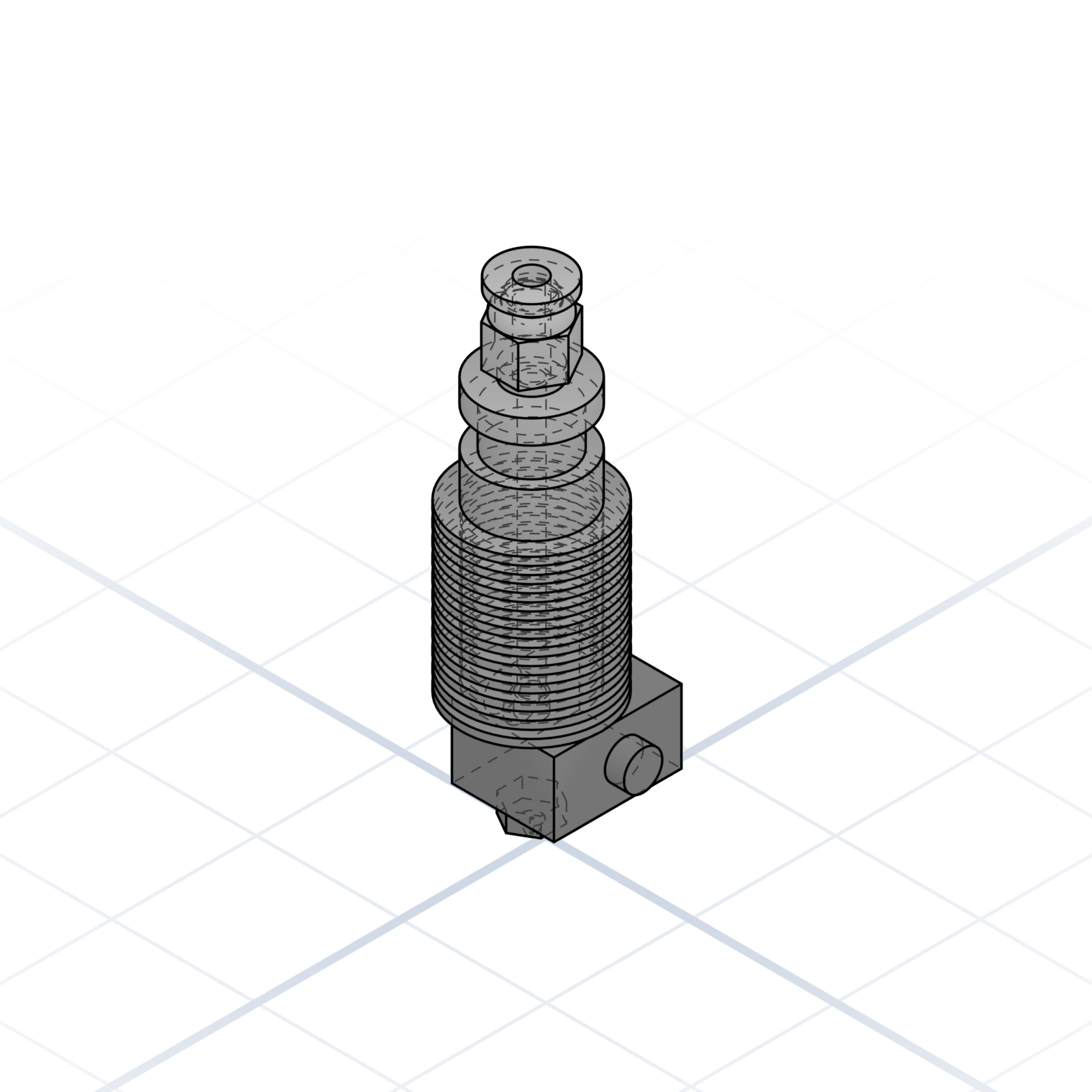
The classic DIY form factor: M6 nozzle thread and a grooved neck on the heatsink. Printed mounts clamp the 12 mm groove instead of threading into the hot end.
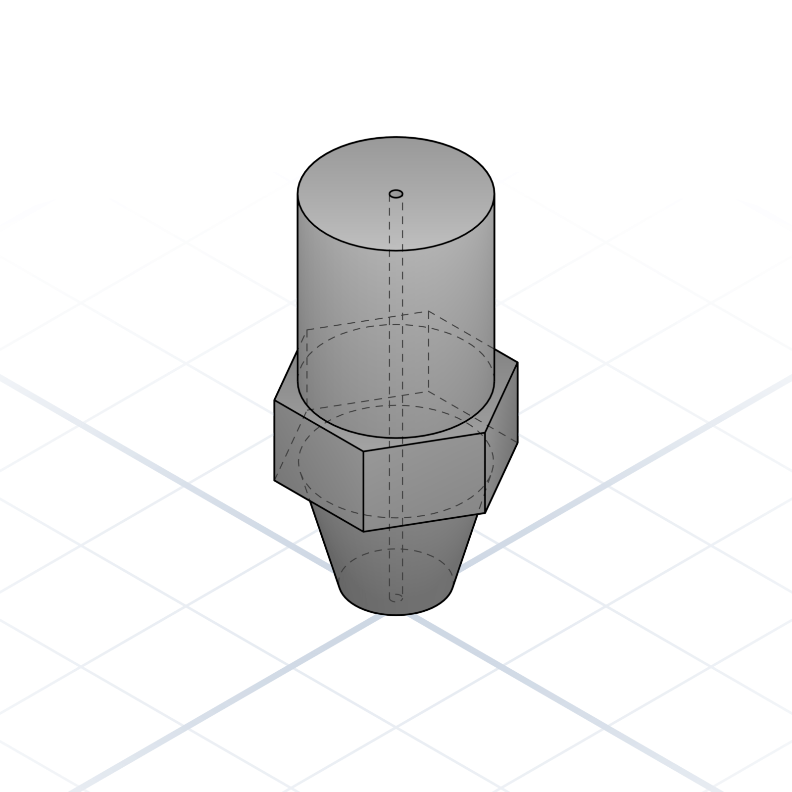
Brass or hardened steel tip, sized by orifice. 0.4 mm is the everyday default; 0.6 / 0.8 for speed, 0.25 for detail.
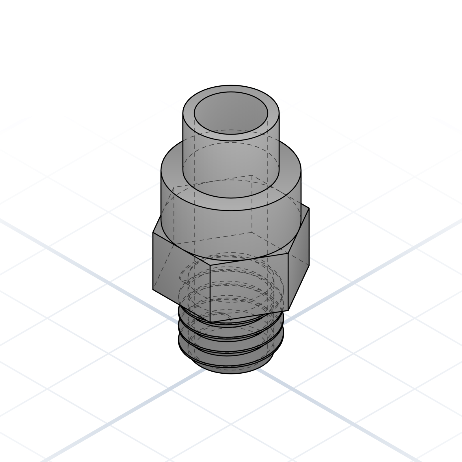
M6 fitting that grips a 4 mm PTFE tube; press the collar to release it. Say “push-fit M6”. Handy in your own designs too, such as a filament dry box.
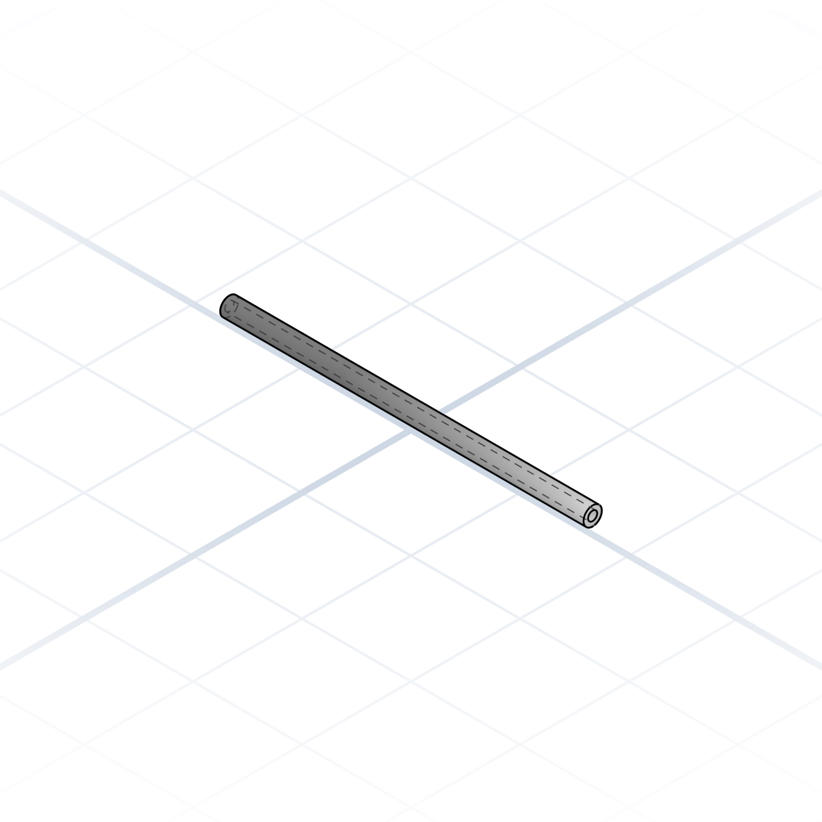
4 mm OD, 2 mm ID Teflon tube. On Bowden printers it connects extruder to hot end; on direct drive it still guides filament from the spool to the print head.
When I was a kid he built me things from whatever was in the workshop. A wooden bazooka. A spinning top. A box that opened a particular way. None of it came with instructions. He just made it because I’d asked, or because he had fun doing it.
He’s why I like making things. He’s why this project exists.
Thank you, Franc.
If this helped
Pass it along to someone just starting out. The vocabulary travels further than the lesson.
Feedback and corrections: grandpacad.com/contact
The vocabulary in this booklet is what CAD designers use every day. Put it in your prompts and the model gets sharper on the first try.
The cheatsheet is free. The build is yours.