Image to 3D model: photo, sketch or drawing to a printable file
Describing a part in words is hard. You know what it looks like, you might even have it in your hand, and still the sentence comes out as "a cylinder with a hole in the top but slightly offset to the left and...". So show it instead. Drop a photo, a napkin sketch or a technical drawing into the chat, add the few numbers the picture can't carry, and GrandpaCAD builds from that.
Since this post first went up (December 2025) the image path has split in two, and that split is the thing worth understanding. A drawing or a sketch becomes a parametric CAD part: exact dimensions, every measurement a slider. A photo of an object becomes a sculpted mesh: the real shape, in color, ready for an AMS. The agent reads the image and picks the path. Below are three real runs from this week, uncut, so you can see what each path produces.
A technical drawing becomes a parametric part
This is a four-hole mounting flange, drawn the way a drawing office would hand it over: a front view, a section, a title block. Ø90 plate, 8 mm thick, four Ø8 holes on a Ø70 pitch circle, a Ø36 hub bringing the part to 20 mm, a Ø12 bore with a Ø20 counterbore 6 mm deep, R2 where the hub meets the plate. The whole prompt was "Model this flange exactly as drawn in the technical drawing, all dimensions are in mm. Printable, single part."
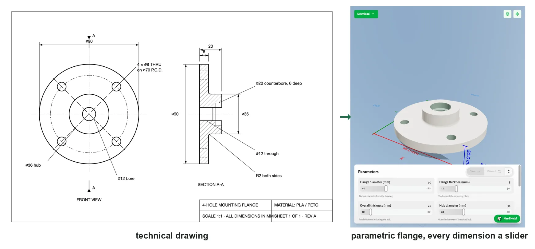
The agent read the drawing, said what it was going to do (match every dimension, including the recessed centre hole and the 2 mm rounded junction, flat face on the bed), built the part, rendered it, and checked the outside and the centre cross-section against the section view before handing it over. Its summary lists the Ø90 plate, the 8 and 20 mm thicknesses, the Ø36 hub, the Ø12 bore with its Ø20 recess 6 mm deep and the four Ø8 holes on the Ø70 circle, every number as drawn. Hole sizes are kept exact, with no printing allowance added, and it says so.
What you get is not a mesh traced off a picture. It's a parametric model with twelve sliders in the panel on the right: flange diameter and thickness, overall thickness, hub diameter, bore, recess diameter and depth, mounting hole diameter, pitch circle, hole count, hole pattern rotation and the junction radius. Moving one re-runs the build on the server without spending a generation. The drawing gave the agent the shape; the sliders are how you make it yours.
A napkin sketch becomes a part, after two questions
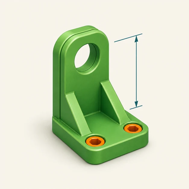
Sketches work the same way, except a sketch usually leaves things out. This one is a cable holder: a block with four cable slots on top, "20 mm" and "100 mm" scribbled next to it, and a side view of the snap-in profile.
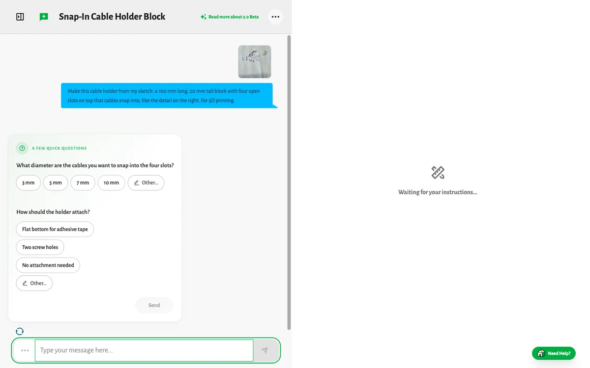
Before building, the agent asked two things the sketch didn't say: what diameter the cables are, and how the holder attaches. I tapped 5 mm and two screw holes. It then picked an 18 mm width on its own, added small relief cuts so the slot edges can flex around a 5 mm cable, and suggested a slightly flexible filament.
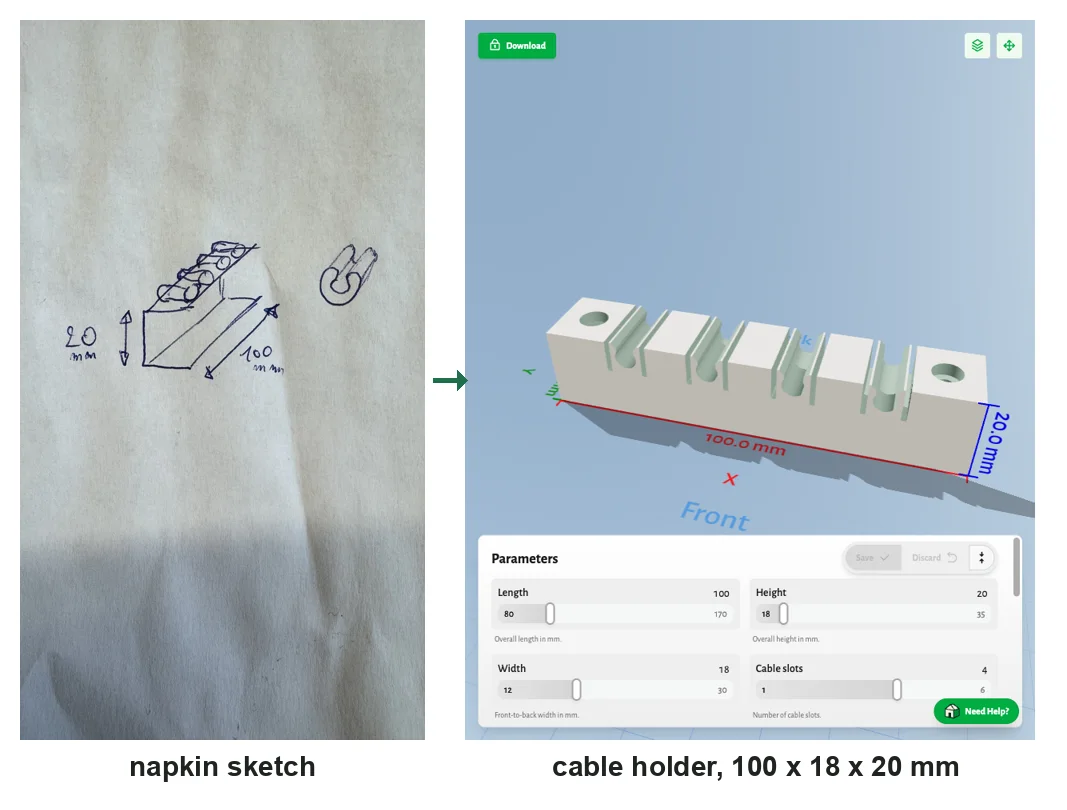
That's the division of labor for sketches: the drawing carries the shape and whatever numbers you wrote on it, the chat carries the rest. If you'd rather not be asked, put the numbers in the prompt.
A photo becomes a figurine
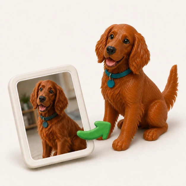
Photos go down the other path. There is no code that produces a corgi, so the agent uses Organic Mode: the photo becomes a clean reference image, the reference becomes a mesh, and the mesh is sized, solidified and colored for your printer. I took this photo on the kitchen floor and asked for "a figurine of my dog from this photo, about 8 cm tall, in three colours for my AMS so I can print it."
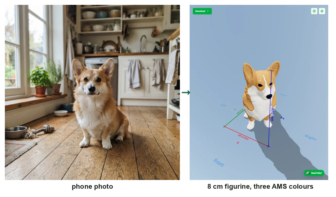
It came back 80 mm tall, as one solid body, split into tan, white and black regions that Bambu Studio and PrusaSlicer map straight to filament slots. The agent ran the printability checks and told me to look at the chin and chest for small supports. About a minute of waiting.
A few things that make photos work better:
- One subject, as much of it visible as possible. A dog half behind a sofa comes back as half a dog.
- Say the size. "8 cm tall" is a measurement the engine sets exactly; without it you get 18 cm on the longest side.
- Say the colors, or the count. "Three colours" splits the model into three flat regions. "Single colour" gives you one material and nothing to repaint.
- Chunky prints better. Vinyl-toy proportions survive a 0.4 mm nozzle; whiskers and leashes don't.
If the first result is close but not right, don't start over. "Make the ears bigger" or "give it a collar" edits the reference image and re-sculpts, and the same shape at a different size, color count or triangle budget is quicker than the first run because the engine reuses what it already built.
Both at once
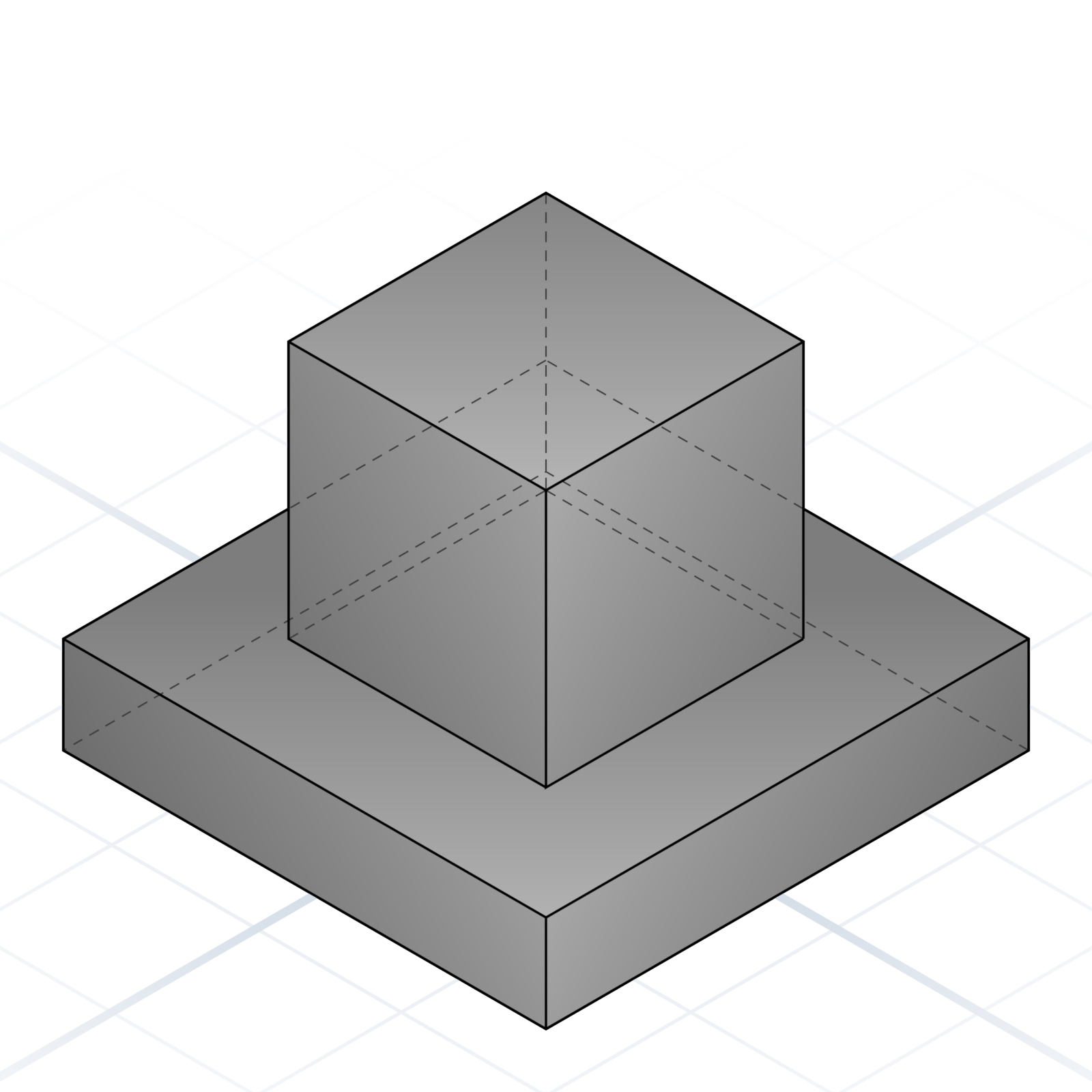
The two paths aren't exclusive. Since the 2.0 agent, a sculpted shape can sit on a parametric part in the same chat: a dog's head on a bottle stopper whose thread is exact, a bust on a base with your name engraved, a figurine on a Gridfinity bin.
Draw it to scale instead
If you have no photo and no sketch, there's a drawing board inside the chat. Every line, circle, slot and polygon on it has a real size in millimeters, rough shapes snap to clean ones, and you can type an exact dimension into any label. Attach the drawing and it goes in as a dimensioned reference, which is the best input of all: the shape and the numbers in one picture.
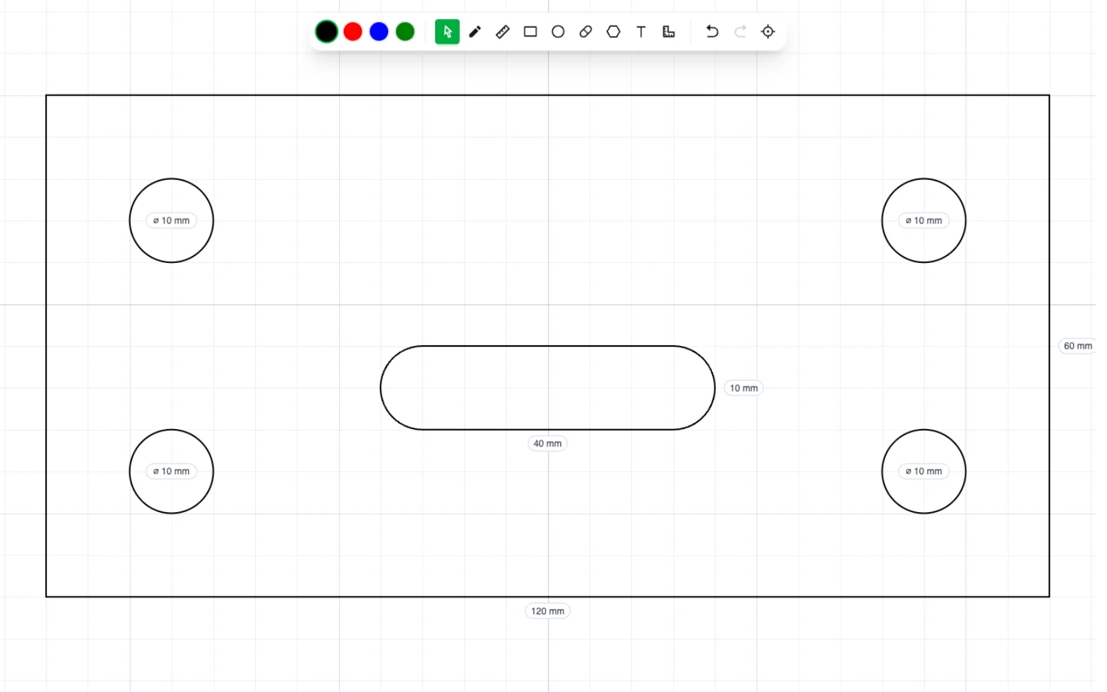
You can also trace over a photo on that board, pulling real dimensions off a rough reference. The sketch mode post walks through the tools.
Mark up a photo
Sometimes the picture is right but the agent should only look at one part of it. Click an uploaded image to open the editor and drop markers on the bits you want built, changed or ignored. The markers go in with the image.
Or bring the file you already have
An image isn't the only thing you can drop in. Upload an STL, 3MF, OBJ or GLB (from Printables, a scan, your own CAD) and say what you want: "make it 120 mm wide", "split it so it fits my bed", "add my name to the base", "it's full of holes, fix it". The agent measures the file first and tells you what it found, then changes only what you asked for, in the format it arrived in. A badly broken mesh can be rebuilt into one solid through the same engine that made the corgi.
What you get back
Every model downloads as 3MF, STL, OBJ or GLB, converted in your browser. 3MF keeps the filament colors for your slicer, GLB keeps a painted texture for a game engine or Blender. If you use ChatGPT or Claude, the same image paths work through the GrandpaCAD MCP server: attach the photo in your assistant, get the file back.
New accounts get three generations, no card needed.