3D printing tolerances and clearances
Short answer: a well-calibrated desktop FDM printer holds roughly plus or minus 0.2 mm in the XY plane, and for two printed parts to fit together you size the gap by how they need to move. The rule of thumb is about 0.2 mm of clearance on diameter for a snug push fit, about 0.4 mm for a part that slides freely, and about 0.6 mm or more for a loose, rotating fit. Those are the numbers most people are looking for, and they line up with the fit names in our Tolerance & Fit Calculator. The rest of this post explains where they come from and, more importantly, why you have to calibrate them on your own machine.
One thing up front: FDM has no hard ISO tolerance grade the way machined metal does. The accuracy figures below are service-bureau specs, and the clearance values are community conventions that have shaken out over years of trial and error. They're good starting points, not guarantees. Your printer, your filament, and your slicer settings will shift them.
If you want to skip the reading and just get a fit dialed in, the Tolerance & Fit Calculator turns a target fit into a clearance number for you.
How accurate is FDM, really?
It depends on the machine class and the part size.
| Machine class | Typical tolerance | Floor |
|---|
| Desktop / prototyping | ≈ ±0.5% | ±0.5 mm, whichever is larger |
| Industrial FDM | ≈ ±0.15% | ±0.2 mm |
| Well-calibrated desktop (real world) | ≈ ±0.2 mm in XY | convention, not a spec |
Notice these are percentages with a floor. That's because error scales with size. A 20 mm part might come out within a couple tenths of a millimeter, but a 200 mm part can drift more as it cools, since thermal shrink runs anywhere from about 0.2% to 1% depending on the material. Bigger parts, bigger absolute error. Plan for it.
Clearance between mating parts
This is the table you'll come back to. These are starting points for a typical 0.4 mm nozzle on a desktop printer, measured as clearance on diameter: the total gap between the two mating surfaces, or the difference in diameter between a hole and the pin that goes in it. They use the same five fit names as our calculator and the printed cheatsheet, so the numbers match wherever you look.
| Fit | Clearance on diameter | Use it for |
|---|
| Press fit (interference) | Shaft ~0.05 to 0.15 mm bigger than the hole (negative) | Permanent joins forced or pressed together |
| Transition (snug) | +0.1 to +0.2 mm | Parts that stay put but come apart by hand |
| Sliding | +0.3 to +0.5 mm | Drawer rails, pistons, sliding lids |
| Clearance | +0.5 to +0.8 mm | Hinge pins, axles, bolt clearance holes |
| Loose | +0.7 to +1.0 mm | Cable pass-throughs, covers, snap-on caps |
A press fit means the hole is actually smaller than the pin (on a filament printer, make the shaft about 0.05 to 0.15 mm bigger than the hole), so you have to force or heat the parts together and they stay put for good. Fair warning: interference fits are unreliable on FDM, because the layer lines and slight dimensional wander make the real amount of interference hard to predict. If you need a tight mechanical grip, crush ribs (small ~0.2 mm bumps that deform on assembly) are more forgiving than a plain press fit.
There's also a smarter way to think about clearance that AON3D advocates: instead of fixed millimeters, scale your gap to about 1 to 2 times the extrusion width. If you print with a 0.4 mm nozzle most of the time, the fixed numbers above are basically that already, but the nozzle-relative version travels better if you swap nozzles or change line widths.
Why FDM can't hold CNC tolerances
If you're coming from machining or injection molding, FDM tolerances will feel loose. CNC and injection molding routinely hold ±0.025 to 0.1 mm. Standard FDM is roughly 5 to 10 times looser than that, and it's directional. Here's what's fighting you:
- Layer lines and staircasing quantize the Z axis. Your vertical resolution is your layer height, full stop.
- Elephant's foot bulges the first few layers outward where the part meets the bed, so the base is slightly bigger than the model.
- Thermal shrink and warp pull dimensions in as the part cools, somewhere around 0.2% to 1%.
- Anisotropy means XY accuracy and Z accuracy aren't the same. A hole is not equally round in every orientation.
- Holes print undersized by roughly 0.1 to 0.3 mm, thanks to inner-perimeter over-extrusion and shrink.
That last point is why screw holes need special handling. I've broken the full metric chart (clearance holes, tap drills, insert sizes) out into the metric screw hole size chart if that's what you're after.
Material also matters a lot here. PLA is fairly stable, but higher-shrink materials like ABS and nylon move more, and you often have to scale the model up to compensate. I dug into that specifically for PLA in the PLA shrinkage post.
Just print a quick test
Here's the honest truth about every number on this page: the only way to know your machine's real tolerance is to measure it. Filament brand, nozzle, flow calibration, cooling, print speed, even ambient temperature all move the result.
So before you commit clearances to a real part, print a small tolerance test. The classic design is a reference pin next to a row of holes, each one a slightly bigger gap, so you print it once and feel by hand which hole gives the fit you want.
You don't have to model that yourself. Describe it to GrandpaCAD and it generates the test part for you, with the pin size and the step between holes left as adjustable parameters. For example:
A 3D-printer tolerance test coupon: a flat plate with one 10 mm reference pin and a row of holes next to it stepped at +0.1, +0.2, +0.3, +0.4, +0.5 and +0.6 mm clearance, so I can print it once and check which hole fits the pin.
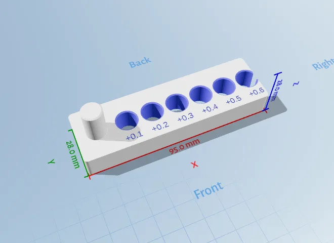
Generated by GrandpaCAD from the prompt above. Each hole steps the clearance by 0.1 mm, and the pin diameter and step size stay editable as parameters, so you can retune the test for a different pin without redrawing anything.
If it's screw holes you care about, ask for those directly instead:
A test plate with clearance holes for M3, M4 and M5 screws at close, normal and loose fits, each hole labelled, so I can see which one my screws actually drop through.
Print it, try the fit by hand, and now you have real numbers for your own setup instead of somebody else's. Re-run the test whenever you change nozzles, switch filament, or redo your flow calibration. It takes ten minutes and saves you a pile of failed parts. For the rest of the tuning (flow, E-steps, shrinkage scaling), the free 3D printing tools collection covers most of it.
Let GrandpaCAD handle the clearances
Once you know the clearance you want, you shouldn't have to hand-edit every mating dimension. Describe the assembly to GrandpaCAD ("a box with a snap-on lid, 0.3 mm clearance on the lip") and it generates the CAD with the gaps already built in. Change your mind on the fit and you just say so.
Sources & further reading